There really is no reason, it's a personal choice.Why shouldn't I insulate the terminals?
However, some commercial products do use heat shrink tubing in those situations to improve vibration resistance and gravity strain relief.
I think you did a great job on the wiring and everything else.
Time to enjoy the music!

The terminals have large contact surfaces, so I stripped them. I could have used heat-shrink tubing with adhesive, but woven electrical tape works too!
Die Anschlüsse haben große Kontaktflächen, deshalb habe ich sie abisoliert. Ich hätte Schrumpfschläuche mit Klebstoff verwenden können, aber gewebtes Isolierband funktioniert auch!
Die Anschlüsse haben große Kontaktflächen, deshalb habe ich sie abisoliert. Ich hätte Schrumpfschläuche mit Klebstoff verwenden können, aber gewebtes Isolierband funktioniert auch!
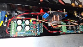
I'm Peter, from the Netherlands. Some 20 years ago I bought the basic LM3875 kit from Peter Daniel, intending to build the kit as dual mono with my 2 Hypex transformers ( with CT !! ). But these are not like the ones Peter uses and now I didn't know how to handle that. This and 149 pages of info on the kit ( AND other stuff Dac's and such ) on this forum was, at the time, a bit much to distill the needed info from. So it took me 20 years to complete this project. I read about different combinations and placement of caps, snubber, or not to snubber, zobel networks, or not and I got confused and stalled. But than I got a little help from a Dutch audioDIYforummember and was able to use the supplied PS pcb's. Decided to use the standard layout and bought a case and some stuff needed and started the build, which took let's say a week to build. I'm surprised at how good it sounds. It's so simple, so little components used, but sounds really nice. I'm using it with Fostex FE103e horns, I built myself. Really nice combo.


Finished! Added led's and the transformermounts.


Last edited:
Here's an LM1875 amp I made with my daughter during Covid. It powers a pair of DIYSG Helix Dome speakers that we also built during Covid. The amp schematic is from the datasheet and the PCBs are my design. Lots of leftover parts went into this. I used SMP supplies that will run off everything from a couple of car batteries in series up to 240v AC. I made my own soft soft and the fan is on a switch. It makes reasonable sounds (not audiophile quality but was a fun project).
The paint is sparkle teal. The speakers are done in sparkle purple.


The paint is sparkle teal. The speakers are done in sparkle purple.
- Home
- Amplifiers
- Chip Amps
- Chip Amp Photo Gallery