How did you do that?Reclock to 1200Khz made sharpness of sound MUCH better vs 400KHz. Temp rising is +10degree celcius max. Just try.
Sent from my Nexus 5X using Tapatalk
Reclock to 1200Khz made sharpness of sound MUCH better vs 400KHz. Temp rising is +10degree celcius max. Just try.
How did you do that?
Sent from my Nexus 5X using Tapatalk
Change some pin connections.
Attachments
How did you do that?
Sent from my Nexus 5X using Tapatalk
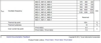
Datasheet: fOSC Oscillator frequency: AM2=1, AM1=0, AM0=0 1200kHz
Just cut AM2 from ground and connect to VDD. That's all.😎
Got some samples from Wurth to test.
Now we talking!
Quick test I have hard to tell Volt+ apart from Sanwu!
Have only made the 20db mod running it with 24v SMPS.
Very low noise, in same level as Volt+.
Adding a bad pic.
i like this testing scheme of simple substitution like you , drmod plus others yielding highly leveraged results.
im thinking next step possibly the subjective testing phase.
Reclock to 1200Khz made sharpness of sound MUCH better vs 400KHz. Temp rising is +10degree celcius max. Just try.
This increases the THD level quite alot.
Putting pin1 high maybe has less thd penalty and might be preferred by all that ignore speakerload and complain about treble.
Interesting.
Why do you think the THD increased when the frequency went up?
Which harmonics went up - lower, upper or all in general?
Why do you think the THD increased when the frequency went up?
Which harmonics went up - lower, upper or all in general?
Interesting.
Why do you think the THD increased when the frequency went up?
Which harmonics went up - lower, upper or all in general?
Because measured and due to increased switching/losses. Mainly rise in D3.
Because measured and due to increased switching/losses. Mainly rise in D3.
I didn't take accurate measurements after overclock with APTA.
But RMAA shown decrease of overall distortion ~ 0.08%.
Anyway overclocked sound seemed to me more natural, especially at highs, than stock 400KHz.
Maybe distortion @D3 is pleasant to ears? Like any tube preamp?
Got feedback from the lab regarding those cheap 3118 on the sanwu fake boards. Die is different compared to 3118 samples from TI.
So good to hear that the chip is confirmed to have authentic die and great work with measurements doctormord! 
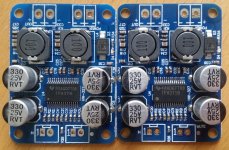
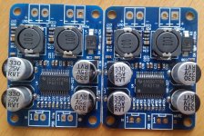
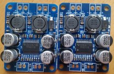
I made some funny findings when comparing boards I have. Some time ago I ordered few boards from Ebay and all chips had serial number 4AAD6TTG4
Later I ordered 4 more from the same seller with same price and to my surprice this time all chips had unique S/N:
53AGQ7TG4
3CCC4YTG4
3CCC5CTG4
41AR7QTG4
Chip markings also vary regarding the position of TI-logo and the dot in the lower left corner. Comparing boards to previous ones, there is also differences in cap markings (fuzzy/sharp), silk screen colour (4AA... has darker) and ESD bag.
I'm not too worried about dies inside the new chips, just wondering if they are running out of 4AA... stock or new people playing with chip markings. 🙄
Attachments

Lately there has been talk about cutting the "bottom trace" between input neg. and power ground. After mutilation of one board I can still measure short between these two points. What exactly should be cut and how to verify the cut with DMM? I would highly appreciate a picture from this operation. 😱
Attachments
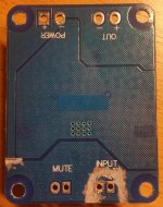
Just the cut on left side. You will still measure short because analog groundpin tpachip is still connected to inputground, but it is a single connection then.
So good to hear that the chip is confirmed to have authentic die and great work with measurements doctormord!
I made some funny findings when comparing boards I have. Some time ago I ordered few boards from Ebay and all chips had serial number 4AAD6TTG4
...
Chip markings also vary regarding the position of TI-logo and the dot in the lower left corner. Comparing boards to previous ones, there is also differences in cap markings (fuzzy/sharp), silk screen colour (4AA... has darker) and ESD bag.
My contact at TI says:
TI does actually do some legitimate manufacturing in China in our own Fab with very good quality control. If we find counterfeits it would be the first time I've seen class-D copied! But almost every product that generates a profit has been copied so far, so it's just a matter of time.
They do indeed seem to be identical with rev letter D2. Therefore #2 is probably not a fake. Packaging may have been done at a different site, making the dot look different. Some packaging sites use laser marked dots, and some use molded.
For TI and other IC companies that I’ve worked for, packaging and testing are done at different factories than the IC fab. TI uses both internal and external sites for packaging. It’s quite possible that the TPA3118 is qualified to be packaged at multiple sites.
Okey, that's reassuring info. 🙂
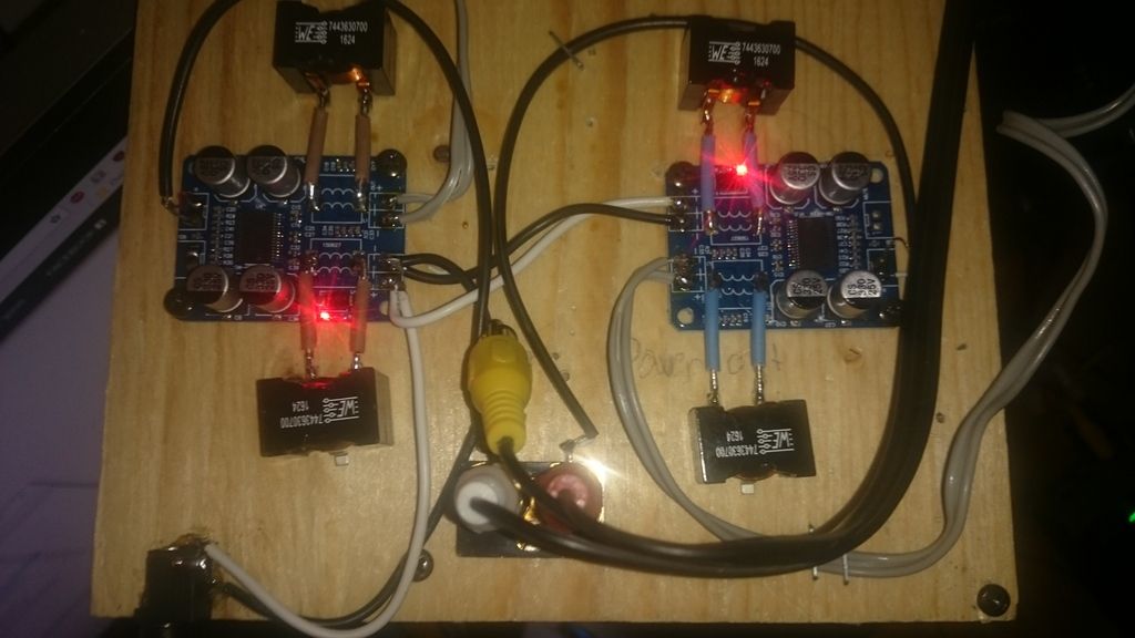
Having holiday and some time to play around. I noticed I get hum, if I use one SMPS for two boards. Both boards are set to 20 dB gain. Hum disappears when inputs are shorted individually, but reappears when input grounds are connected together. I'm using mini plug - stereo RCA cable as connection to source (PC has female plug connection).
I assume I'm creating a loop from the mini plug that goes through board, power supply and back. At the moment I'm testing with two power supplies, one for each board and everything looks good. I guess using input transformer would also solve the problem, but I haven't seen any cheap ones (or atleast with reasonable shipping fees).
So I'm asking more simple (cheaper 😉) solutions when using existing source. Would bringing source signal ground straight to PS negative DC out with one wire, skipping amp inputs, be a good idea? That would create star ground point when using only one PS and everything should be nice and dandy sound quality wise?
- Home
- Amplifiers
- Class D
- Cheap TPA3118D2 boards, modding them and everything that comes with it