Hey guys, I've been lurking in this forum for a little while, thinking what mods I should incorporate into my own board..
Anyway, performed some major mods today, in hopes of decreasing (completely eliminating) the hiss/white noise I could hear in the background, as well as maybe decreasing the overall temperature caused by inefficient inductors...
The problem - I did not reach any of my "goals", and I am looking for some help.
So, a few questions:
- Are SMD capacitors equally good/better than through hole? I'm using GRM43DR72E224KW01L as bootstrap caps, had some trouble soldering them... and I can't really tell if there was any improvement over the originals... Do cold (or otherwise bad) solder joints cause any problems/distortions?
- Can the background noise be caused by the ~10cm unshielded input wire, or is it more likely that it's internal? Since everything is on my workbench right now, I have a 10cm wire coming from the potentiometer... just wondering if that could be the cause and would it improve after mounting it in the case, and using ~3cm wire...
- What are the nominal amp/inductor working temperatures? Measuring it with a cheapo Chinese IR thermometer, chip runs at 40C and inductors are at a whopping 60C. (Ambient air temp is 30C, and everything is on an open bench) I'm just worried about frying everything after mounting it in a case...
Attachments
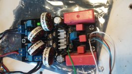
With ceramic bootstrap caps - the material makes a difference. Np0 and c0g is better here compared to x7r - there may be lower distortion with former. Even better are film caps rated at higher voltage.
It's the Sanwu TPA3118D2 PBTL boards I have.
If I look at your post #3689 it's after C10 and C12 in the closeup.
Do I need only these?
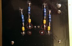
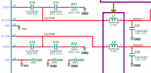
Without pulling up schematic from data sheet all I an say is that it needs to connect where the bootstrap connects to the chip. Hence the name bootstrap snubber - this is same as point going to inductor input.
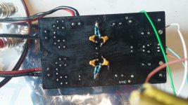
Hi Dalius98, Do you have the snubber connected correctly ?
I think I do - from the "output" of the bootstrap capacitor/ "input" of the inductor to the ground plane... Does something looks wrong with it?
I have three of these (Sanwu monoblocks) that I'm trying to fit into a small case I had on hand for use in driving right, left, and center speakers I'm adding to my TV. I thought I could put pin-headers on the modules and then fly a piece of protoboard over them for interconnection.
I was pretty pleased with the plan, until I realized that the power and output connections have an odd pitch. ~4mm or so. Any educated guesses on what kind of connectors they were designed for?
I was pretty pleased with the plan, until I realized that the power and output connections have an odd pitch. ~4mm or so. Any educated guesses on what kind of connectors they were designed for?
Are the caps for the snubber connected to the "outside" legs of the bootstrap caps ? I do realise that your board is not identical to the YJ BB and this is an assumption on my part.

I think I do - from the "output" of the bootstrap capacitor/ "input" of the inductor to the ground plane... Does something looks wrong with it?
Are the caps for the snubber connected to the "outside" legs of the bootstrap caps ? I do realise that your board is not identical to the YJ BB and this is an assumption on my part.
My board is the cheapest Chinese knock-off I could find, so no wonder it has different layout.
But I have triple-checked this - snubber capacitors are connected to that side of the bootstraps, which connects to the inductors. (Checked with a continuity tester). And as far as I can tell from the schematic, that's how they are supposed to connect 🙂
Attachments
This might not be the best place to ask, but I couldn't find a better one 🙂
So I made this amplifier + headphone switch, and I am having some problems...
While connected to my home PC, amp/speakers emit a high pitched noise, which to my understanding is coming from all the electronics/cables surrounding it... (since I can hear my mouse movements).
The interesting part is, that there is no such noise (or very minimal?) when connected to my workshop PC, or when I am using headphones. And that's using the same cable for input.
What could be the solution to this? Would using a higher input impedance (50K pots?) help? (Currently using cheap Chinese 10K pots...)
Or could this be a ground loop issue? I'm not so sure how they sound, as I did not manage to find a suitable audio sample... Although both the PC and the power for the amp are connected to the same power source (an UPS). And it's strange that this problem disappears on another computer...
Honestly, it's my first audio project, and I have no idea what is wrong...
If it is a ground loop, it's probably because the amplifier board treats the power input ground the same as audio input ground, and that way both of these get connected through the case connectors or something... but I am just speculating here...
Attachments

----//----
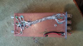
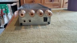
Alright, so it was definitely a ground loop issue, got around that... Learned a lot in the process, so it was worth it. Now there's just a tiny little bit of hiss which goes away in the last 1/4 of the potentiometer travel, so I guess it's because of my cheap pots...
Attached are the pics of a "finished product", pretty proud of myself, lol.
Attachments

its not because of cheap pots; its because this chip does not like varying input impedance, which is what your pot does.
my solution is to use digitally controlled analog volume control, such as the pga2310, 2311 or cs3310. these provide constant output Z and attenuate before an output follower/buffer. THAT is the secret.
you will always get varying noise via a pot since its not constant output-z and some amp circuits don't do well with variable input Z.
put a proper buffer between your pot and the amp and that will fix the noise (variation).
this is known as 'prebuffering' (or postbuffering, depending on where you are viewing).
Oh, that's good to know - saves me from buying quality pots for testing 🙂
Although I can't even hear the noise from more than 20cm away, so I think I'll just live with it. The whole reason I bought this cheap amp and went the DIY route was because I wouldn't be able to tell the difference between a quality amp anyway.
Thanks to everyone participating in this forum, you are the only reason I have a semi-decent audio setup now, instead of buying some logitech computer speakers again...
you can still do an easy DIY preamp with a module like this:
PGA2311 Stero Remote Volume Remote Controller Preamp | eBay
its $35 or less and gives a very low noise and digitally controlled line-out. I'm using that board now and having good luck with it.
I am using my own controller for it, which has tuned software to drive the PGA chip. you could use the included ebay controller, it works ok, but its not the best thing you can get. I like the LCDuino style controller (I wrote the firmware and designed the hardware; its buyable as a kit at amb.org) and I have instructions coming soon on how to modify things so that the new controller talks to the existing ebay PGA board.
you should consider it. not only does it give remote control, but it solves the noise issue and gives input selection, as well (and an lcd display, IR control, motor pot support, etc).
Decided to also dive in with these little guys, so I ordered 2 of the 'Sanwu' boards on eBay (although they do not say so on the product itself) together with a 24V power supply I saw mentioned on here before.

(the €0,50 is so a colleague would believe how small they are 😉)
They got here in a week time, so have the main components already, but still waiting for all the stuff around it like connectors etc.
But now that I have them in my hands a question popped into my head: are there any do's or don'ts when it comes to the layout I need to keep in mind? Of course keep signal and power wiring separated as much as possible, but do I run the risk of the coils in the power supply interfering with the amplifier modules if I do the orientation wrong for example?
Also contemplated mounting the 2 modules on top of each other with standoffs, so the wiring will become easier to keep separate That way power is on top of each other, input and output are also, so they do not have to cross if I route them logically.
Last edited:
Standoffs and stacking.... If running 24V and near full cap, you'll need a heatsink. Also, they're HF switching devices.... Stacking might work but equally, it may turn out horrible. Use LONG standoffs... I suppose another option is back to back on a common heatsink. 🙂
Alright, so stacking might not be the best idea.
Heatsink mounting is not as easy as it sounds with this type of packaging. Probably stick a small one on top, or mount the whole board (insulation in between) with its back on a bigger heatsink?
Will try how hot it gets on low level first ofcourse.
Heatsink mounting is not as easy as it sounds with this type of packaging. Probably stick a small one on top, or mount the whole board (insulation in between) with its back on a bigger heatsink?
Will try how hot it gets on low level first ofcourse.

Alright, so stacking might not be the best idea.
Heatsink mounting is not as easy as it sounds with this type of packaging. Probably stick a small one on top, or mount the whole board (insulation in between) with its back on a bigger heatsink?
Will try how hot it gets on low level first ofcourse.
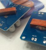
I soldered these copper spreaders directly to the thermal vias.
The heat sink on these boards is ok but I noticed the topside seem to have a fast temperature rise compared to the bottom pad.
So maybe needed a lower thermal resistance.
-
Attachments
- Home
- Amplifiers
- Class D
- Cheap TPA3118D2 boards, modding them and everything that comes with it