Hi
sorry for that I don't have any pictures of this, but here is my measurements, of the
"TPA3118 PBTL mono digital amplifier board 1X60W 12V 24V" :
(with gain R27-resistor removed, because of noice in speaker when normal gain)
-------
Line in: 2v (just before clipping)
Vcc: 23v (about)
resistor: 8ohm
out: 20v
(smoking HOT after about 30 seconds !!)
[ [20/(scr(2)] ^2 ] / 8 = 25w
_ _ _ _
Line in: 1,5v (about) (just before clipping)
Vcc: 23v (about)
resistor: 4,4 ohm
out: 16v
(smoking HOT after 30 seconds!!!, verry verry hot!!)
[ [16/(scr(2)] ^2 ] / 4,4 = 29,1w
_ _ _ _
Line in: 1,02v (just before clipping)
Vcc: 11,5v (about)
resistor: 4,4ohm
out: 8,8v
(not hot after 30 seconds)
[ [8,8/(scr(2)] ^2 ] / 4,4 = 8,8w
_ _ _ _
Can I cool this with a "ready solution" for the coling??
any ideas for a functional solution ?
I have also found out that my minidsp2x4 deliver max 0.9Vrms (in 4 ch) and not 1.41Vrms (2v) or not 1.061 (1.5v), 😢
I have no good solution for this, have any one any ideas?
I have to decide what to do about the mismatched pair of boards I have.
how many variations of parts values do I have to check? I can verify all the printed resistor values and that's easy. I can't know what cap values they may have used since those are not marked. if I want to try to 'match' modules, do I need to care about the caps possibly being different (the smd ones) ?
it may be easier to remove and replace the parts that need to match, rather than sending the module or modules back to the seller.
I'm sure this is going to happen again and again, too, so I guess I should know how to 'match' the modules, regardless of what gain setting they came with from random sellers.
I have to decide what to do about the mismatched pair of boards I have.
how many variations of parts values do I have to check? I can verify all the printed resistor values and that's easy. I can't know what cap values they may have used since those are not marked. if I want to try to 'match' modules, do I need to care about the caps possibly being different (the smd ones) ?
it may be easier to remove and replace the parts that need to match, rather than sending the module or modules back to the seller.
I'm sure this is going to happen again and again, too, so I guess I should know how to 'match' the modules, regardless of what gain setting they came with from random sellers.
I would not worry about matching anything beyond the gain resistor settings and maybe the output filter caps/inductor for your specific speaker impedance. You won't notice much with the others if they came from factory with SMT parts.
I use the small Sanwu tpa3118 boards in combination with a 24 Volt/12 Ampère linear power supply, a high quality Delta Elektronika M24-12HE. (These powersupplies are rather cheap in the Netherlands on the secondhand market.)
I do not use a preamplifier; my Iqaudio dac is directly connected with the Sanwu boards and the Sanwu boards are directly connected with my B&W DM5 speakers. I use the TPA3118 boards in stock form and the sound is very good, no problems.
I read in the forum a lot about the 20db gain mod (removing R27). Should I do that? Or is it my case unnecessary? Will the sound be different when I do this mod?
I hope someone can answer this question from a not very technical music lover!
First listen to 3118 board
Bypassed one of my Helder Tripath amps in my OB with a 3118 board/ 19v and then 24 volt supply. Very accurate sounding, somewhat "bright" on the high end. Ran pretty hot at 24v but heat sink will fix that, also much louder than the tripath amp. Checked the gain resistors -100k and 30k guessing the gain should be about 28-29db with that combination. Moving now to a permanent hook up with 24v supply.
Pete
For me the biggest difference was that the noise level in low volume listeningI use the small Sanwu tpa3118 boards in combination with a 24 Volt/12 Ampère linear power supply, a high quality Delta Elektronika M24-12HE. (These powersupplies are rather cheap in the Netherlands on the secondhand market.)
I do not use a preamplifier; my Iqaudio dac is directly connected with the Sanwu boards and the Sanwu boards are directly connected with my B&W DM5 speakers. I use the TPA3118 boards in stock form and the sound is very good, no problems.
I read in the forum a lot about the 20db gain mod (removing R27). Should I do that? Or is it my case unnecessary? Will the sound be different when I do this mod?
I hope someone can answer this question from a not very technical music lover!
almost disappered.No difference in sound just lower max output.
As you sad, it's "bright".Bypassed one of my Helder Tripath amps in my OB with a 3118 board/ 19v and then 24 volt supply. Very accurate sounding, somewhat "bright" on the high end. Ran pretty hot at 24v but heat sink will fix that, also much louder than the tripath amp. Checked the gain resistors -100k and 30k guessing the gain should be about 28-29db with that combination. Moving now to a permanent hook up with 24v supply.
Pete
Only problem with this amp.
No mod in this brightness?
"no mod for this brightness?"
My electronic skills are no match for the size and complexity of these tiny amps. Perhaps a tube lineamp might take the edge off it. Seen many of them on Ebay, for a few dollars might be worth the effort.
Pete
My electronic skills are no match for the size and complexity of these tiny amps. Perhaps a tube lineamp might take the edge off it. Seen many of them on Ebay, for a few dollars might be worth the effort.
Pete
Bootstrap snubber mod may take edge of brightness. Also larger input caps - 4.7uF will extend bass and maybe balance it more. Just bypass on board SMT input cap with wire soldered on and add 4.7uF 63v film cap outboard right beiges amp.
"May take edge of brightness"Bootstrap snubber mod may take edge of brightness. Also larger input caps - 4.7uF will extend bass and maybe balance it more. Just bypass on board SMT input cap with wire soldered on and add 4.7uF 63v film cap outboard right beiges amp.
Love you xrk971 for all you know and you'r solutions, but the bootstrap mod
on TPA3118D2?
How to do it?
🙂
330pF Np0 or C0G SMT cap and 10R SMT resistor. Connect to trace between bootstrap cap and inductor as close as possible to chip, or connect to solder pad on input end of inductor. Or use small 1/8w axial resistor and radial ceramic cap and dead bug solder to input end of inductor. It's tight but the bootstrap caps are exposed.
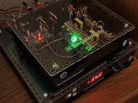
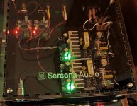
some pics of yesterday's TPA3118 build (unit is on top of my older, existing LCDuino relay atten preamp).
I tried to do a fairly neat job this time (lol). nice silicone flexi wiring (from my quadcopter hobby) and 2 of those DROK amazon 24v supplies. I even splurged for nice terminal blocks and properly crimped connectors. white wire is neutral and black is hot (and fused and switched). there is nothing to connect green ground to; not sure if it makes sense to have a 10ohm/.01uF ground-breaker from rca shield to power ground or not. for now, left it floating, but protected with a dummy quick connect terminal.
I might change the led colors, though 😉 maybe make them all the same color; and my front power switch is a blue illum thingie, so maybe it should all be a blue color theme.
at some point I might also add a controller for remote control, muting, fault detection, over-temperature detection.
Attachments
some pics of yesterday's TPA3118 build (unit is on top of my older, existing LCDuino relay atten preamp).
Nice build, thanks for posting!
Any listening impressions?
Did you do any modifications to either the amp boards or the PSUs?
Those SMPSes are very similar---though not identical---to the one Jensen567 talked about earlier in this thread. He was able to improve their performance a bit with some light modding. Based strictly on appearance, I'm guessing the same mods would likely benefit your SMPSes.
Some more general questions: what do you get by using one PSU per amp board, as opposed to one shared PSU for both amp boards? (Other than more power, obviously, assume you could get a single PSU with 2x the current capability of the two you used.)
Also, when you put a PSU (SMPS in particular) in the same case as the amp boards, does it make sense to try to protect the amplifiers from any EMI/RF noise created by the power supplies? If so, how would one go about accomplishing this?
Nice build, thanks for posting!
Any listening impressions?
I have average hearing and to me, these sound as good as anything else I've heard. once things are 'competant' (and its not hard to get to that level), after that its all the same to me. wish I could hear the 'magic' that others say they hear, but beyond 'good!' I don't hear this vs that sounding any different. I hear more diffs in material and mixing/mastering/micing than I do in electronics. I'll hear major diffs in spkrs and headphones, but once electronics are 'good' - I don't need to go beyond that.
I think that's why I'm now more interested in the efficient 'switching' amps (d, t, whatever). I'm giving all the A and AB style amps a rest (lol) and will live with just these for a while and see if I have any issues.
the benefits to me are huge. takes up less space, less weight, each module is a module on its own and since they are cheap enough, if they blow I swap a new one in. no heat throw-off to speak of, no fussiness about psu needs, they are easy to wire up and they don't need DUAL RAIL (wow, I hate that with a passion) supplies.
there, that explain my feelings well enough? LOL!
Did you do any modifications to either the amp boards or the PSUs?
Those SMPSes are very similar---though not identical---to the one Jensen567 talked about earlier in this thread. He was able to improve their performance a bit with some light modding. Based strictly on appearance, I'm guessing the same mods would likely benefit your SMPSes.
don't know about those mods. have a link handy? if its easy, sure, I'll give it a try. will I notice the improvement? probably not. but if its easy and it corrects some things, sure, I'll go for it.
I've had those psu's for a short time, just a week or two. they seem ok. I know that ones that look like this are all over: ebay, amazon, etc. I went with amazon for ease of shipment, returns, problems, quality control. in fact, one of the psu's that I ordered was 'delivered' by amazon next-day for me and it never got here. I called amazon and they sent a replacement truly next-day and I had it that next day, sure enough. if you are a 'prime' member, amazon bends over backwards to help you. ebay is just the opposite and if I'm dealing with long distance shipping across country borders, forget it. usually not worth the hassle unless its sourced only from over there.
amazon will be doing well, I predict, as there are probably lots of people who feel the way I do. we'll pay a few dollars more for that service, as long as we are buying one-off quantities.
Some more general questions: what do you get by using one PSU per amp board, as opposed to one shared PSU for both amp boards? (Other than more power, obviously, assume you could get a single PSU with 2x the current capability of the two you used.)
Also, when you put a PSU (SMPS in particular) in the same case as the amp boards, does it make sense to try to protect the amplifiers from any EMI/RF noise created by the power supplies? If so, how would one go about accomplishing this?
every time I tried combining boards with a single psu, I got some oscillation or swishing noise. I did not try putting one module into slave mode (which maybe is what you HAVE to do if you parallel supply them?) - but I wanted to leave the modules as stock as possible and since a psu is $15 or less, spending time THINKING about it costs me more than the module. lol.
there's no down side to going full mono. everything OTHER than full mono is a compromise. for $15? come on. the modules are mono, why not go all mono, at least in this box. (ok, I didn't go dual IEC inlet. that would be funny. no, I don't plan on that) 😉
oh, and as for the proximity of the switching psu to the boards, I did the orientation as best I could and in actual use, I don't hear any real hum issues. the background hiss is always there. when I tried a single mono module with the cleanest 12 or 24v dc supply I have, the noise is still the same. that proved to me that there is no benefit to a 'clean' linear psu when you go into a switching amp like this one. why waste linear and trafo on something that is going to eventually 'destroy' (lol) the signal anyway?
the board is well laid out, it puts the input on one end and the output+psu on the other. perfect. can't ask for better. and so I made my box just like that and the orientation of the flow really dictated how the main elements of the chassis would be. next iteration, I'll clean up some rough placements and make it even more optimal for signal path.
keeping the distance from the psu to the amp is a critical point for me, in philosophy. once you exit a regulator, you want to keep that loop short. I didn't go nuts doing that, but I kept that in mind and did what I could with the modules that were there. the psu modules were also properly done, ac on one side and dc-out on the other. that defined where my ac inlet would be in the box, and by rule, the rca in has to be at the opposite side, as much as you can.
I'm happy with it, even though it may look 'odd' and some designer who might think of the chassis, first, would demand I move internal things around. but I refuse 😉 I try to get the signal flow and psu and i/o so that it makes as much sense from an electrical POV as possible, still being buildable and fixable, too.
I guess with Class-D, PSU is of less importance than with Class-A(/B).
Is a fact that Class-D already filter it's output, from it's own noise and all the others 😛.
If anything, I would put an inductor in power supply line to filter switching frequencies from SMPS (like my LEPAI 2020+ has - nice touch!)
My TDA3116D2 2.1 feeding two monitors and a "sub" (really, a Creative Labs 'subwoofer' from PC speakers package) draws 0.5W! (constant, with or without music playing 🙄)
But when I go mad, boy, they can draw 2-3 watts !! (mean power)
That's what a system draws in a near-field audition configuration.
My competent SMPS is a 12V 1.5A from an external HDD that acts as a fuse in my power output tests...
I have a 12V 10A SMPS ready to install, but I miss the enthusiasm to do so 😀
If in doubt, I would put more low ESR caps in/near the board than anything else.
330pF Np0 or C0G SMT cap and 10R SMT resistor. Connect to trace between bootstrap cap and inductor as close as possible to chip, or connect to solder pad on input end of inductor. Or use small 1/8w axial resistor and radial ceramic cap and dead bug solder to input end of inductor. It's tight but the bootstrap caps are exposed.
Ok, long time from China but got some 330pf.
Do I connect them at all pins?
I mean from pin 20,24,26,30 from the chip?
Four 330pf and four 10R?
Last edited:
Ok, long time from China but got some 330pf.
Do I connect them at all?
I mean from pin 20,24,26,30 at the chip?
Four 330pf and four 10R?
You won't have enough room right at the chip pin - it's ok to move out a bit closer to the input to the inductor. Scrape off some of solder mask over the thick travel from chip to inductor. Solder 330pF the 10R in series then to ground. On PBTL I think only 2 snubbers are needed.
Intentional purpose has signal flowing from inductor to snubber, signal flow is from inductor back towards chippins, intended signal source for snubber is inductor, not chip.
It's the Sanwu TPA3118D2 PBTL boards I have.You won't have enough room right at the chip pin - it's ok to move out a bit closer to the input to the inductor. Scrape off some of solder mask over the thick travel from chip to inductor. Solder 330pF the 10R in series then to ground. On PBTL I think only 2 snubbers are needed.
If I look at your post #3689 it's after C10 and C12 in the closeup.
Do I need only these?
- Home
- Amplifiers
- Class D
- Cheap TPA3118D2 boards, modding them and everything that comes with it