Hi X
Yes, I just received it. Thank you very much! You sent me a gift upon the gift.😍 At first, I want to build this amp so I can compare the sound to the original. Thank you one more time! Greatly appreciated.
Yes, I just received it. Thank you very much! You sent me a gift upon the gift.😍 At first, I want to build this amp so I can compare the sound to the original. Thank you one more time! Greatly appreciated.
Still Not ready ...
I Hope i have some free time next days
Preamp ist designed
Then i saw that you can Order Aluminium PCBs with one layer for Same price Like Double layer FR4 ... So i Changed Layout for Output Buffers ... 😂
now i have FR4 Main PCB with Volume ...
and small Buffer PCBs of this Lender preamp in single layer Aluminium PCB
Check Layout again and then ordering PCBs ..
Last edited:
I used aksa Lender schematic and created a new Layout (with 0805 Bridges ) single sided
This can be produced on Aluminium PCB
And a Second Variant with a Diamond Buffer Stage. These are Modules with same connection to Mainboard ..
so i can Test two different Output stages
This can be produced on Aluminium PCB
And a Second Variant with a Diamond Buffer Stage. These are Modules with same connection to Mainboard ..
so i can Test two different Output stages
Cool, you are fast. I think these were the IMS (integrated metal substrate) layouts JPS64 had made already:

It’s a nice preamp stage.
so you are still using the CFH11 LTP front end. You just wanted an additional preamp to drive it? It’s got sufficient gain already if I recall.
It’s a nice preamp stage.
so you are still using the CFH11 LTP front end. You just wanted an additional preamp to drive it? It’s got sufficient gain already if I recall.
LolCool, you are fast. I think these were the IMS (integrated metal substrate) layouts JPS64 had made already:
View attachment 1014133
It’s a nice preamp stage.
so you are still using the CFH11 LTP front end. You just wanted an additional preamp to drive it? It’s got sufficient gain already if I recall.
I didn't know this Layout..
But my Version is similar to this board
No.. there ist no additional preamp to Drive it
Power amplifier is finally Planed.
No additional gainstage ... Only Input
Gain is more than enough
The Last Simulation with 1,57Vpp was 68Vpp Output
Preamp uses only simple jfet Buffers or simple gain stages... No OPVs
The Last Stage is a module ... Aksa Lender Module or a diamond Buffer Stage ( similar to DISPRE )
This can be Changed..
I will Check If its Sound different... Or Not ^^
Hi,I got my boards today. 🙂
What are the T1/R1-T2/R2 values? What would you recommend I use? Also what is set with T1 and T2. Thanks in advance for your help.
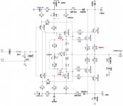
This was the latest schematic as built by Thimios. Not sure what your question is?
The values are in the schematic.

The values are in the schematic.
Hi xrk971No worries. Just wondering if that last layout by Thiago is good to go. If anyone else has built it and got it to work please let me know.
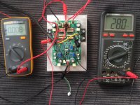
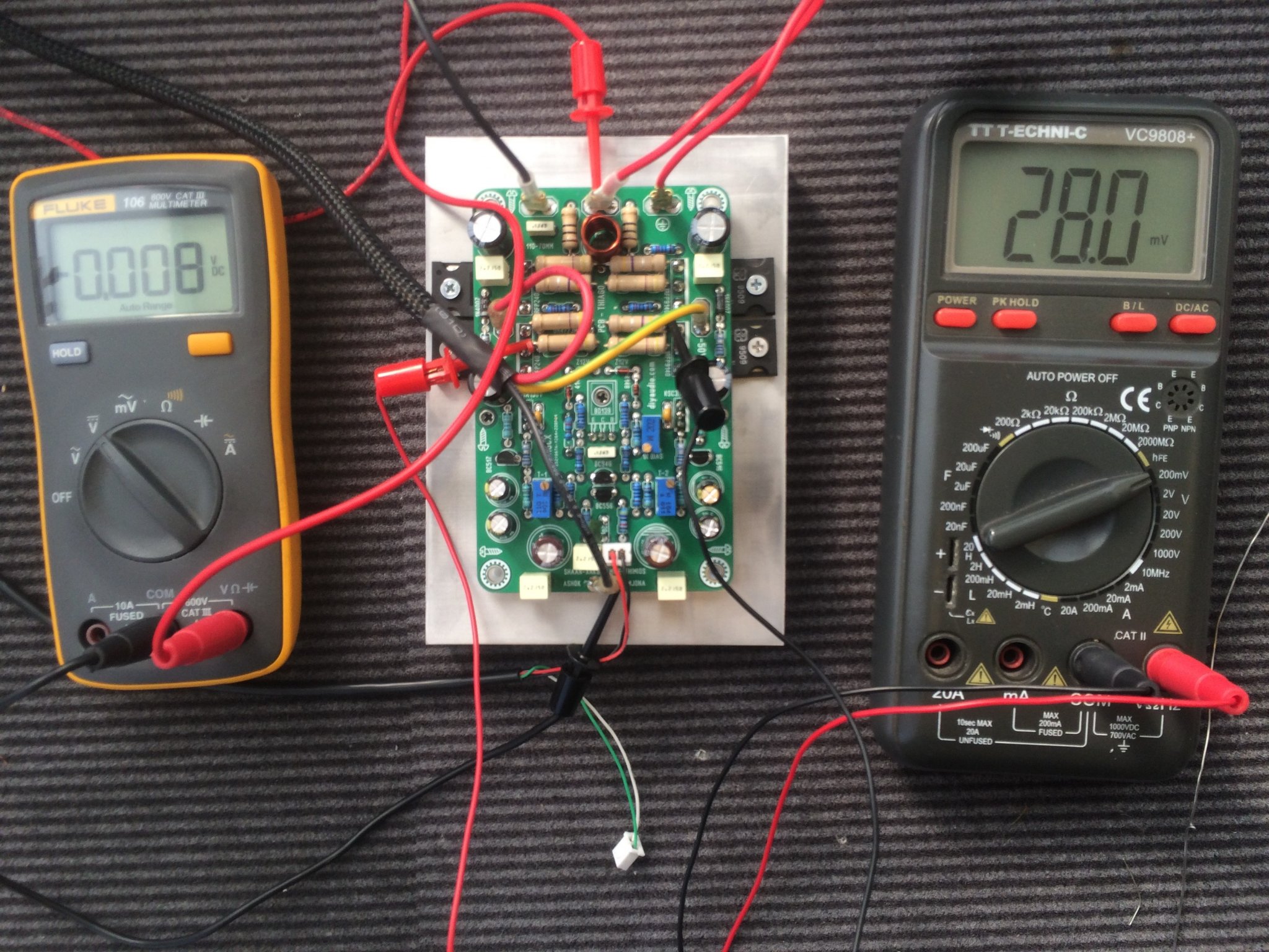
I have finally completed the assembly of the board. no problem. excellent sound. offset voltage:0.008v. quiescent current:28mv.
Thanks xrk971.
Thank you Thiago
Attachments
I would replace the signal transistors with low noise type. You can use there BC550C & BC560C. Same pin out. The 50V max. rail voltage should be low enough to use the mentioned transistors at that place.This was the latest schematic as built by Thimios. Not sure what your question is?
The values are in the schematic.
View attachment 1055394
@fazildiken - Super work! Thanks for showing us that this layout works. It’s a great sounding amp from what I can remember.Hi xrk971
I have finally completed the assembly of the board. no problem. excellent sound. offset voltage:0.008v. quiescent current:28mv.
Thanks xrk971.
Thank you Thiago

@saddevil - did you ever get yours running?
@gaborbela - thanks for the tip on BC550/560 as alternate. I also like KSC1845 and KSA992 (twist legs as needed) as input stage BJTs.
Last edited:
Yes those are also great good low noise signal transistors also. When an amp uses a few parts every parts quality counts. Low noise transistors on the input never hurt.
Tomorrow the last day DISCOUNT price on resistors at PartsConexion, I did planed to order for other(similar) project also.
Because this project came up again and again I will order those few resistors also.
I have a pair PCB, thanks to X!
I also have most of the capacitors and semiconductors at home, why not, lets build it.
I made some tweak on the schematic, I simplified some of those after made connections and I CHANGED some resistor values and the feedback also.
This is how I will build it. Schematics attached.
Opinions welcome.
Attachments
I didn’t design the cap multiplier add on but generally that resistor sets the amount of “ripple reduction”. Get some extra values like 4k7, 10k, 22k - I think the larger value gives lower ripple at the expense of the frequency response to track the faster variations.
47k and 22uF gives a -3dB point of 1.4Hz which is not a bad point to set if one is trying to smooth 50Hz ripple. 10k and 100uF works too.
47k and 22uF gives a -3dB point of 1.4Hz which is not a bad point to set if one is trying to smooth 50Hz ripple. 10k and 100uF works too.
Hi X,
What is the correct schematic for Thiago’s layout of CFH9 pcb? There is a couple versions posted, one also with a Schade influence. Thanks
What is the correct schematic for Thiago’s layout of CFH9 pcb? There is a couple versions posted, one also with a Schade influence. Thanks
Ive seen designs where theres a cap to the gnd between the zener and 10ohm. 0.47uf usually. I never found the explanation for it. Have you tried simming that?I didn’t design the cap multiplier add on but generally that resistor sets the amount of “ripple reduction”. Get some extra values like 4k7, 10k, 22k - I think the larger value gives lower ripple at the expense of the frequency response to track the faster variations.
47k and 22uF gives a -3dB point of 1.4Hz which is not a bad point to set if one is trying to smooth 50Hz ripple. 10k and 100uF works too.
hi Vunce,
I think it’s the same one on post 1036:

At least we know it works as designed:
The oscillations were already handled by Thimios’ mods earlier. This adds the cap Mx for the front end. One thing about that is that you lose some top end voltage to drive the highest peaks due to cap Mx dropout. The cap Mx can be bypassed if one has a sufficiently low noise and hum is not an issue.
I think it’s the same one on post 1036:
At least we know it works as designed:
The oscillations were already handled by Thimios’ mods earlier. This adds the cap Mx for the front end. One thing about that is that you lose some top end voltage to drive the highest peaks due to cap Mx dropout. The cap Mx can be bypassed if one has a sufficiently low noise and hum is not an issue.

Last night I went over on that schematic and looks like that is the correct for the PCB.
I only did not like the previously mentioned resistors. For start I will use a 4k7 type.
I do not think that will influence the sound of the amp "that much".
I only did not like the previously mentioned resistors. For start I will use a 4k7 type.
I do not think that will influence the sound of the amp "that much".
Hi
I have 2 questions IF someone could answer about it would be great.
First question.
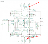
For 12V zener diodes I only have at hand 10V or 13V can I use any of those?? If yes wich one......
Purple arrow on the circuit..
Second question
I only have IRFP9240 Mosfets marked as SEC, I believe Samsung Semiconductor. It is original, purchased at local store many years a go,
similar to the Polida's picture. Picture just for visualization, not from Polida!.
MY question can I use those as a pair for the IRFP240?
Please let me know. Thank you
Greetings
I have 2 questions IF someone could answer about it would be great.
First question.
For 12V zener diodes I only have at hand 10V or 13V can I use any of those?? If yes wich one......
Purple arrow on the circuit..
Second question
I only have IRFP9240 Mosfets marked as SEC, I believe Samsung Semiconductor. It is original, purchased at local store many years a go,
similar to the Polida's picture. Picture just for visualization, not from Polida!.
MY question can I use those as a pair for the IRFP240?
Please let me know. Thank you
Greetings
Attachments
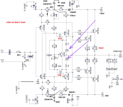

For 12V zener diodes I only have at hand 10V or 13V can I use any of those?? If yes wich one......
This diodes are supposed to protect gates of fets. As far as I know, anything higher than 8.2V will be OK.
I would use 10V.
- Home
- Amplifiers
- Solid State
- CFH7 Amp