Hi Guys,
I took another look at the schematics on LTspice based on the last version by Saddevil. I removed the main rail cap multiplier and reduced some bulk cap values to keep the board smaller. The bias current is running pretty hot at 824mA (412mA per device) for about 90W dissipation per channel. Here is the schematic I am working with:

Look at what we get for performance. At 8Vpp into 8 ohms (1W) there is almost no distortion.

At 50Vpp into 8ohms it still is very low:

At 80Vpp into 8ohms (100W) I am getting THD of 0.001621%.
These are kind of crazy low numbers, that will be larger in real life but these are some of the best simulations I have seen for an 11 active device amp.
I took another look at the schematics on LTspice based on the last version by Saddevil. I removed the main rail cap multiplier and reduced some bulk cap values to keep the board smaller. The bias current is running pretty hot at 824mA (412mA per device) for about 90W dissipation per channel. Here is the schematic I am working with:
Look at what we get for performance. At 8Vpp into 8 ohms (1W) there is almost no distortion.
At 50Vpp into 8ohms it still is very low:
At 80Vpp into 8ohms (100W) I am getting THD of 0.001621%.
These are kind of crazy low numbers, that will be larger in real life but these are some of the best simulations I have seen for an 11 active device amp.
Attachments
Hi to all[/CODE]
I have ordered the PCBs:

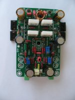
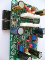
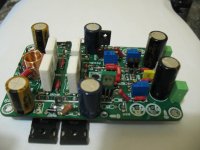
I have an important question about this amplifier, I know many of you built this (PCB picture above). I have the two stuffed PCB without the power mosfets.
My question DO I NEED to VGS match the power mosfets or not that important?
Please someone who built the amp (and use it, like it) let me know. Thank you!
I know some class A/B amplifier can be built (works) with multiple power mosfets without VGS matching but at the cost.
It may degrade the function quality and the sound quality also
I just want to test soon this amp, I thought I ask before I solder the power mosfets into the PCB (I have IRFP240 matched only I need the complementary).
From my experience, parallel mosfets always need to be matched.
Otherwise amp will be oscillating.
Otherwise amp will be oscillating.
OK, that was my fear. Thanks for your answer!
It is a decade or so last time I matched mosfets (I forget it).
When I built my Aleph X I purchased 50PC IRFP240 those are matched them all.
I just purchased 10PC IRFP9240, the complementary those are not matched.
So I need to somehow re-learn how to match mosfets. 🙄
It is a decade or so last time I matched mosfets (I forget it).
When I built my Aleph X I purchased 50PC IRFP240 those are matched them all.
I just purchased 10PC IRFP9240, the complementary those are not matched.
So I need to somehow re-learn how to match mosfets. 🙄
The matching is done.
They are all so close to each-other I thought I'm doing something wrong.
All between 0.635V and 0.640V.
On the end I grabbed couple older mosfets were matched previously to double check and the matching is correct.
I just realized I got 10PC IRFP9140 and not IRFP9240. I will use that with the IRFP240 as complementary.
Thanks one more time for the advise.
Very soon ( not later than next week) I want to power up this amp.
Same way Mr. N Pass instructed us for DIY Aleph amplifiers.
I used the same set up with 150R 5W resistor.
Only difference used 16 VDC not 15V.
My HP printer power supply. I measured voltage not current. The resistor got warm 30 sec. per mosfet.
The IRFP240 was matched the same way into my Aleph 30 and Aleph X also. With out any offset or any nasty oscillation.
Not even started soldering the semiconductors and I already found a setup function error on my PCB. Somehow I have to take care of it. The 100K trimpots (the ones I got, the one they sent me) are not adjustable.
The turning parts are on the side and I have no access to it from the 1000uF capacitor to tune it.
I think will replace it with a 50K, with the adjusting part on the top. I hope it still works..
I see different schematics, some use 18K value there, other 22K values.. I wish I have at home 22K type of resistors, I would get rid of those trimmers. When all matched well there should be no offset!
I do have 50K trimmer plus the 47K resistor parallel is close to the requirement. And my 50K can be adjusted from the top.
I tried to measure (to set up before I mount the PCB on the heatnink) the 100K trimmer parallel with 47K resistor but I cant.
That can be a problem at set up! My DMM just jumping up and up until measure nothing, like I measure an oversize capacitor.
Attachments
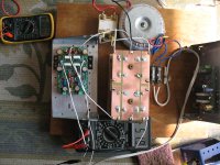
Just finished installing all the semiconductors.
Some places I had to use other type of BJT's I did not have the original.
For example I have only low quality China made BC546B & BC556B,
Instead I used BC550C & BC560C from ON Semi.
I will set up the amp at first around 40V rail voltage and measure the voltage on the mentioned BJTs.
Also for VAS transistor I used Hitachi, I do not have the KSA type at home.
Fingers crossed, hope it all works out.
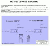
Information / a picture how I matched the mosfets......
Attachments
Hi gaborbela,
That's how we matched output mosfets with Adcom also. It is important to do that. It probably won't oscillate, but current sharing has to be reasonably even.
As for your trimmer controls, you shouldn't ever need 10 turn types. Honestly, the circuit can be set up with resistors and a trimmer to restrict the range to a useful area. Besides, cheap 10 turn controls are going to be an issue in the future as the contacts oxidise more than a single turn type. Amplifiers were successfully designed since the 1960's with single turn controls and I have serviced them. Also, bias is an approximate setting that will vary with ambient temperature, AC line voltage and heat sink temperature. But this is not a precise adjustment no matter how hard you try.
Hi thiagoThanks for the tips and comments lazy cats. I'm from Nelson Pass School and I'm a fan of some harmonized controlled profile. I did not have a good experience with the CFA, I mounted PeeCeeBee, CFH7 and A33 Apex and all 3 found it difficult and lifeless, very accurate, but it was not what I was looking for. all 3 very stable and an incredible bandwidth, plus I still prefer Quasi from Ranchu, ACA with 24v from Nelson Pass and AX11 Apex that sounds incredible to me with a lot of footprint and a sweet sound. I do not want to do a discussion here, but do I want THD too low? Maybe it's my ears, or my speakers. Thank you for VSSA that you introduced the community, without a doubt, an excellent amplifier.
Thiago
What version of AX11 (and PCB) did you build. I'm interested because I did not build an Apex amp.
Thanks in advance for your reply
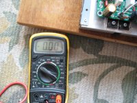
Today I managed to power up one side and set up the bias. No smoke, all do at first start up the bias went up over 2.2A.
I managed with the trimmers to bring it down and get rid of the 4.6 VDC offset also.
Right now I set up the bias 60mA and 0V offset.
Unfortunately the bias keep jumping, moving up and done a couple mA. I can not do nothing with that.
It is weird to see that, nonstop moves up and down 2 to 4 mA. Otherwise it looks like will stay around where is set up (in my case 60 mA).
No sound test, need a potentiometer, speakers terminal some wiring, etc.
I think later I set up the other side.
Attachments
Hi gaborbela,
Bias current is thermal. So it will slowly oscillate up and down depending on a number of factors. In other words, do not worry about it. It will be different tomorrow, but in the ballpark. That is all you really want to worry about.
Good job, time to set the other side up and enjoy your hard work!
Bias current is thermal. So it will slowly oscillate up and down depending on a number of factors. In other words, do not worry about it. It will be different tomorrow, but in the ballpark. That is all you really want to worry about.
Good job, time to set the other side up and enjoy your hard work!
Second channel is set up! No smoke/sparks etc. 🙂
My opinion it is a very compromised idea to use 3 trimmer to set up the (bias) amplifier and get rid of the offset without testing points.
I would use max 2 trimmers! One for bias and one for offset!
Yes I replaced those trimmers from 100K to 50K but that is not a setup problem. Both side I measured about R=22K.
This time when I turned on the power I could not adjust the bias only 5-6mA max.
The two trimmer witch supposed to adjust the offset need it to be adjusted to total opposite way,
Also the bias trimmer needs to turn counter clock wise for up. 🙄
The VAS transistors became hot like burning my finger.
My VAS transistors not mounted on the main heatsink!
On the end I managed to set up but who knows if the negative side we have the same bias as the positive at the front and the end also. 🙁
If there is 3 trimmers we should have some testing points!
I do not want to be ungrateful toward the PCB designer! 3 trimmers I do not like it! Just want to say thank you for the design. 🙂
At the moment I managed the VAS transistors not burning hot by touching it, just warm. The other channel those are only a bit warm.
I do not have a scope to test for oscillation, etc.
Tried to measure the signal transistors voltage and mA but not much room there for measurements.
I do not want to short something accidentally and burn it before the sound test.
Hi gaborbela,
I haven't looked at this design for ages.
In general, you should only need one control for bias current, one for DC offset. There are some amplifiers that don't need a DC offset control and they don't have a DC servo. You just match the diff pairs and you have 10 mV or less DC offset. The Hafler DH100 is one example.
Your Vas transistors (or any transistor) should ideally only get warm at the most. Running these hot will damage the PCB in time, and also cause them to fail or become noisy. So, not a good plan.
Sounds like you're on the right path with your build. Try and buy an analogue oscilloscope (not digital), a 100 MHz dual trace should be a couple hundred $, maybe a bit more for a very good one. These will be far more useful and show you more detail than a digital oscilloscope.
Finally!
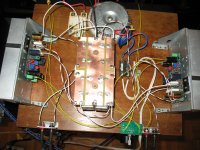
Today I wired up the signals and now both channel on and playing music.
First I made a mistake and one channel was dead silent only I could hear some ripple noise.
I revers connected one of the RCA wire the signal went to the ground.
Again now both channel up and singing.
First CD I play so I can not write about the sound!
Not a bad amplifier, similar to my old faithful Darlington amplifier.
At first impression my amp (the darlington type) more involving has a warmer sound.
This one a bit hard in the mids section and kind of colder. But again the first CD I play.
I run the amp on 39V rail voltage instead 50V, it is a testing time.
Wires are all over, lose, long etc. I do not want to cut those very short before I give her own enclosure.
Yes this amplifier it deserve to be built!!
Not a bad sounding amplifier.
Also I made several modification from the start. I used VAS transistors and signals what I had and I thought it will do the job.
I would describe the sound more transistors like and not a mosfet sound!!
The Darlington sounded more mosfet like, softer ad more involved into the music.
I must be patient and run it for a couple day so the amp break in a bit. Most wires, parts etc brand new!
Thank you X and others who designed the amplifier!
Attachments
I wanted to do some "upgrade" but.......
Wanted to replace the Arcotronics capacitor on the input to 10uF Silmic or MUSE. (I have both at home)
Same time I wanted to increase the rail voltage around 50V or so. I have two transformer one without load gives 39 VAC the other 36 VAC.
Unfortunately I can not do it, just realized some of the power supply caps (Cornel Dubilier) are only rated 50V some (Nippon CC) 63V.
I mix those without paying attention their voltage ratings.
I am frustrated because of that. Build a new power supply? 🙄 🙁
2 pair power mosfet would handle easily 50 to 55V rail voltage.
The heatsink mounted on is cold.
My transformer at the moment 27.5-0-27.5 Volt only. The transformer as warm as the heatsink almost only rated 225VA.
I have some large can capacitors 100V 9800 uF but those I purchased for a special high voltage amp.
I also have other caps but those are 100 000uF Nippon CC. 4 of that over kill in this amplifier. Those large can caps are for Class A amps.
The sound opened up since yesterday (10-12 hours listening), I like the amp enough to give this amplifier an enclosure with some upgrades.
- Home
- Amplifiers
- Solid State
- CFH7 Amp

