A good transistor replacement for BC550C / BC560C with a higher voltage alternative?
Reason I do not use BC546B / BC556B types because it has a low Hfe and I got only cheap Chines (Ebay) type.
I do not care about the pins I will twist to fit.
I want to increase the rail voltage up to 50V or 54VDC. The BC550C/BC560C I use now I think it will surly burn.
Did ever someone replaced BC5## transistors successfully with other type higher voltage?
Any advise? For example 2SC2240BL? (I have at home) MPSA42 / 92?
Please let me know, if you have any idea.
Thank you!
Those have different pinouts (you must twist leads). Choose whether you want to use EBC or ECB pinout, then try using a selector on ON Semi's site, or Digikey.Any advise? For example 2SC2240BL? (I have at home) MPSA42 / 92?
Any transistor not purchased through proper distribution will probably disappoint you. Just buy new and current devices, read the data sheet for the part as some come from different beta ranges.

Thank you very much for your reply. I mention couple of transistors because I have at home and they are sure original.
I also have 2N5401 / 2N5551 from ON Semi.
You know hard to find good quality BC546C / BC556C.
The B type I do not like even if I could find some original. Their Beta half or even less compare to the BC550C/560C.
Thanks one more time, great help!
I also have 2N5401 / 2N5551 from ON Semi.
You know hard to find good quality BC546C / BC556C.
The B type I do not like even if I could find some original. Their Beta half or even less compare to the BC550C/560C.
Thanks one more time, great help!
Try KSC1845 and KSA992. Good for 120v and superb transistors.A good transistor replacement for BC550C / BC560C with a higher voltage alternative?
Reason I do not use BC546B / BC556B types because it has a low Hfe and I got only cheap Chines (Ebay) type.
I do not care about the pins I will twist to fit.
I want to increase the rail voltage up to 50V or 54VDC. The BC550C/BC560C I use now I think it will surly burn.
Did ever someone replaced BC5## transistors successfully with other type higher voltage?
Any advise? For example 2SC2240BL? (I have at home) MPSA42 / 92?
Please let me know, if you have any idea.
Thank you!
I did check some of the mentioned transistors pin-outs.
The best (and easiest) to use 2N5401 / 2N5551 pair would be. Just rotate 180 degree.
Many amplifier use those transistors even here on the forum. For example the SARA amp.
The KSC1845 and KSA992 I like also but need to be rotated and twist the pins to.
I will change one channel at the time and will do a listening tests.😎🙂
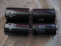
Will put together a higher voltage capacitor bank, it is a Class A/B amp, no need to be 100 000 uF or more.
Right now I use 4Pc 18 000uF and 4Pc 15 000uF capacitors bank. Even that is over kill but the problem some rated only 50V.
I found some older (used but good condition) capacitors 2pc 18 000uF and 2pc 15 000uF, that will do the job. Of course they are 63 and 71 volt type.
I will reuse those.
The best (and easiest) to use 2N5401 / 2N5551 pair would be. Just rotate 180 degree.
Many amplifier use those transistors even here on the forum. For example the SARA amp.
The KSC1845 and KSA992 I like also but need to be rotated and twist the pins to.
I will change one channel at the time and will do a listening tests.😎🙂
Will put together a higher voltage capacitor bank, it is a Class A/B amp, no need to be 100 000 uF or more.
Right now I use 4Pc 18 000uF and 4Pc 15 000uF capacitors bank. Even that is over kill but the problem some rated only 50V.
I found some older (used but good condition) capacitors 2pc 18 000uF and 2pc 15 000uF, that will do the job. Of course they are 63 and 71 volt type.
I will reuse those.
Attachments
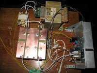
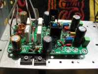
I exchanged the power supply and I set up one channel with BC546B & BC556B ( from Farchild)
Even the B type has double the beta than the 2N5401 / 2N5551 pairs!
I removed the Arcotronics 2.2uF capacitor from the signal path I replaced with 10uF Silmic capacitor.
That made the bright / shiny mid range disappeared.
The music / mid-range more involving much more natural.
That is an improved on the sound but the signal transistors not as good as the BC550C / BC560C from On Semi.
I miss some of the deep bass some of my other amplifiers has.
To give you a real evaluation I have to modify the other channel and set it up.
Looks like (I have that feeling) it will be not my favorite amplifier!
Last couple month I built 5 amplifier these is the less preferred at the moment. Some of those are Class A amps!
Al do not that bad, enjoyable I believe the original Darlington is better if is built with care!!
Main reason I built this amp to compare it!!!
Only problem with the the darlington transistors reliability. They tend to fail time to time can take your woofer to! Speaker protection degrade the sound..........
Some circuit problem I think
When I set up the one channel I tried to balance out the bias on the negative rail and positive to be the same.
I measured the voltage true the 5W resistors.
It is impossible to get the same mV on both side. The positive side it is always double or more!
It does not mater how I adjust it.
I need to set up both channel to figure out if I keep working on it or not.
I do have many other projects to finish or work on them.
Attachments
Thanks for your listening impressions. The bass would be mostly a matter of output impedance / damping factor. Use thicker and shorter high strand count 16ga silicone insulation RC drone battery wires from your PSU to the amp and use at least 22mF per rail. Also, change mosfet source resistors to 0.1ohm vs 0.22ohm.
I use 33 000uF per rail now. Before I used 56 000uF (the 50 Volt).
I can change the source resistors, I think I have at home 0.1R 5W type. I have to check it out.
At the moment I use 14 & 16AWG teflon wire. Mostly 16 AWG.
I do have 12AWG but hard to work with. Very stiff / rigid.
Most of my Class A amp Pass F5, Musical Fidelity I use the same wires.
Thanks for the advise.
Since I powered up it get better a bit!
Those PS capacitors did not see power for a many many years.
I have to be more patient, you know when you have an amp sound better you are less patient with the others.
At the moment my bias 100mA.
ANATECH Totally I agree with you.
Once we use the proper parts, wire, capacitors etc it is almost impossible to upgrade changing those or adding more!
The Circuit, bias plays BIGGER role here.
I am not saying I totally luck the bass. Compare to some of my other amp yes I have much less and different.
Some of those are Class A amp or heavily biased like the Cubie3 (0.55A bias). Pass F5, Musical Fidelity A1 clone....(Class A all the way)
At the same time I have the Kaneda amp only 60mA bias with an excellent deep bass!
It look like needs more time to break in, she got a bit better since yesterday morning after the work I have done and I powered up.
I worry about the VAS transistors they run too hot for my likening. I have to try to ad a small heatsink. Almost burns my finger to touch.
Yes, the Vas xistors are too hot.
To be honest, class A amps have the same faults as A-B amps. An iffy A-B design can sound better if the bias is cranked, but a good A-B amp design often sounds better even with minimal bias current. I have one that only needs 5 mA per output device, bipolar. A single device class A has different problems and higher distortion.
Many really good commercial designs have their best performance with output bias current in the 20 ~ 50 mA range. 20 mA is generally a good, safe level. You don't see crossover distortion until levels drop much lower in good designs. This is an observation over decades looking at just about every design out there.
Those VAS transistors were meant to be mounted underhung to the heatsink. Thats what the screw holes are for - to access a hex socket cap screw to bolt it to the same heatsink.
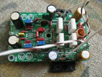
I set up the second channel, replaced the signal transistors to BC546B / BC556B, the input capacitor from 2.2uF Arcotronics to Elna Silmic 10uF.
This channel next to the 2200uF capacitor has a bypass green ERO 3.3uF capacitors.
That point is very sensitive to the sound quality at the Darlingon amplifier. (This amp and that they are same family).
I added two small heatsink on the VAS transistors.
Let see if it takes away some of the heat. My Darlington's VAS runs almost cold to touch with the same (100mA) bias!
Today just listening music, it is my birthday I do not want to do much more on this amp.
After both channel settle done (couple days) I will do an A-B test let see ERO caps or no ERO preferred.
I may (test to) reduce the 2200uF value also. My Darlington has 220uF Silmic only and has much more airy sound!
This has a 2200uF Panasonic FM type (not bad)
I also run out the signal wire I used in my other amplifiers, this yellow solid wire with teflon I use here not the best wire compare to that.
Attachments

I know, I am sorry that screw holes does not feet for my heatsink fins.Those VAS transistors were meant to be mounted underhung to the heatsink. Thats what the screw holes are for - to access a hex socket cap screw to bolt it to the same heatsink.
The PCB lifted up like 8-10 mm from the heatsink. You know the component leads under the PCB..........
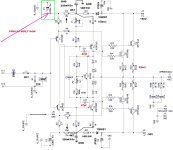
Today I was ready to order some Silmic capacitors to try to replace the one I marked on the schematics.
Unfortunately even the 1000uF 16V has a 16mm dimension (to big). Max room I have on the PCB 12mm.
My question
What if I replace that capacitor with an organic / solid capacitor. They are small in size!
I have a project USSA3 where Fab uses and advise to use organic / polymer capacitors with his project.
Any idea? Or just waste of money?
I thought to ask before I order. How I stated in my Darlington amp that capacitor quality is very influential to the outcome of sound quality.
Did ever someone used organic capacitor to replace electrolytic caps?
Thank you!
Attachments
Hi gaborbela,
Coupling caps will not change the sound. Leave the originals unless there is something wrong with them.
Poly-Aluminum capacitors have some different characteristics that may cause problems in some circuits. Read the data sheet carefully, look at the circuit and decide. I'm not going to give you the answer, figure it out. All I'm going to say is, pay close attention to the entire data sheet.
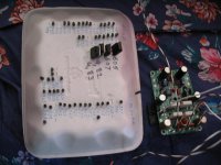
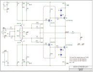
Here is the mentioned USSA3 (current feedback) amplifier with organic / polymer capacitors. Many DIY-ers use those caps in that project based on Fab's advise! My amplifier not finished yet!
I do not want to hijack the thread, just want to improve somehow the sound of this amplifier.
At the moment I do not want to accept (defeat) is not possible. I invested to much time and some finances to just to give up......
I will bypass the power supply caps also with larger polyprop. caps.
The sound still too bright for my likening, not involving enough, I miss some deeper bass also.
This when I compare to some of my other DIY amplifier in a A/B test not just a feeling.
Attachments

- Home
- Amplifiers
- Solid State
- CFH7 Amp