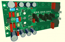
I got my boards today. 🙂
Please do not forget me 🙂, Thank you.
Greetings
Hi Ganborbela,
Of course - thanks for the reminder. Do you still live at the same address in Toronto? Please send me your address via PM to make sure and I’ll send it out to you. If you are interested, I’ll throw in the FH9HVX too.
Of course - thanks for the reminder. Do you still live at the same address in Toronto? Please send me your address via PM to make sure and I’ll send it out to you. If you are interested, I’ll throw in the FH9HVX too.
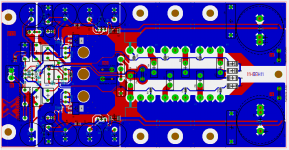
I haven’t checked your pin out on SOT223 vs TO126 on drivers but assume you have it right. I would make the common bus from drivers to each mosfet gate stopper resistors larger. It’s too skinny and could have a voltage drop between the three MOSFETs.
I would have made it same thickness as the connector between the two diodes on the same path. There’s no reason to be thrifty with the trace width as you have lots of room on the board.
A large Pad with very Low current can make some Problems
the larger area can absorb more interference than a smaller track
For small Signals it does not make sense to use large areas
But the track must be large enough to handle current and have Low resistance and inductance
For Gate Signals ... I will Check... I think 1,2-1,4mm is possible
the larger area can absorb more interference than a smaller track
For small Signals it does not make sense to use large areas
But the track must be large enough to handle current and have Low resistance and inductance
For Gate Signals ... I will Check... I think 1,2-1,4mm is possible
Last edited:
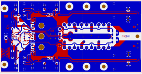
now with 1,8mm
and also VSA has larger traces
EDIT: added pdf
and also VSA has larger traces
EDIT: added pdf
Attachments
Last edited:
Hi Saddevil,
Thanks so much for your hard work on making this amp layout! Looks great. I hope more people give this a try. I will order some boards with my next batch of PCBs.
Thanks so much for your hard work on making this amp layout! Looks great. I hope more people give this a try. I will order some boards with my next batch of PCBs.
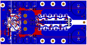
i checked footprints and it seems that all transistor are ok now.
if i have some time , i will upload a BOM ... so it is easier to collect all parts
and i will order 5PCBs too
actual values are designed for SMD version ...
i will upload a schematic for THT version
some resistors a a bit different
if i have some time , i will upload a BOM ... so it is easier to collect all parts
and i will order 5PCBs too
actual values are designed for SMD version ...
i will upload a schematic for THT version
some resistors a a bit different
I ordered 5pcs in china 🙂
we will see . rest of the parts are here , both for SMT and THT version
i will build both and measure a bit
hope they are working like expected ^^
we will see . rest of the parts are here , both for SMT and THT version
i will build both and measure a bit
hope they are working like expected ^^
This amp has plenty of gain already so almost anything with decent line level can drive it.
The Aksa Lender is a superb preamp if you need one that can swing 40Vpp.
If all you need is buffering and bal/SE conversion with fixed gains 0/6/14/20dB the BTSB is great.
But if your goal is to give the sound some soul of a SE Class A amp with 0.05% second harmonic and 12dB less third and nothing else, try the DCA or the Hakuin. Both can be obtained as Yarra/M2X daughterboards. You can build a nice Yarra PSU and input selector. Or use the Yarra breakout board.
My personal favorite is the Hakuin topology designed by Hugh Dean (Aksa).
I have a question.. I see some improvement on the schematics but the same time the front end was simplifies? Is it not worthy to ad (to keep) the extra par small BJT at the front? Please see the picture in the red box. That was an improvement over the simplified front end. Reason I ask I see work on the PCB still in progress. This in one older version with Toshiba mosfets (uses same footprint as hexfets )

it works also like expected ^^
i did not see any THD improvements compared to resistor or zener variant
but it helps a lot to stabilize at different main voltages.
without this stabilisation the circruit works only at 50V
with your CCS or with zener ist works good from 40-55V
the drift without this stabilisation is very crazy
i did not see any THD improvements compared to resistor or zener variant
but it helps a lot to stabilize at different main voltages.
without this stabilisation the circruit works only at 50V
with your CCS or with zener ist works good from 40-55V
the drift without this stabilisation is very crazy
Did you receive the package yet?PM sent. Yes the same address.
Greetings
- Home
- Amplifiers
- Solid State
- CFH7 Amp