next try ...
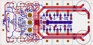
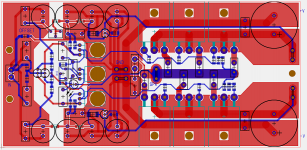
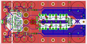
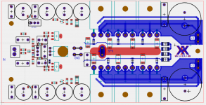
which one would you prefer ?
plane or no plane
with an additional plane on TOP layer i have to place tons of vias to connect the planes together
regarding skrews ...
yes the 3 drivers are a bit painfull
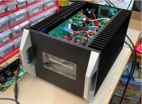
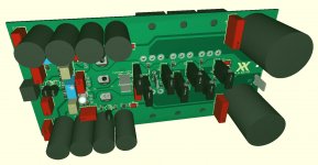
the mosfets are fixed with PCB to heatsink ... there is no problem i think.
to make it easier -
1: place parts below PCB wihout soldering ,
2: mount to heatsink
3: solder all parts
4: cut the pins
with 68Vpp @ ~72mA per Fet ( x3 )
which one would you prefer ?
plane or no plane
with an additional plane on TOP layer i have to place tons of vias to connect the planes together
regarding skrews ...
yes the 3 drivers are a bit painfull
the mosfets are fixed with PCB to heatsink ... there is no problem i think.
to make it easier -
1: place parts below PCB wihout soldering ,
2: mount to heatsink
3: solder all parts
4: cut the pins
with 68Vpp @ ~72mA per Fet ( x3 )
Harmonic Frequency Fourier Normalized Phase Normalized
Number [Hz] Component Component [degree] Phase [deg]
1 1.000e+03 3.445e+01 1.000e+00 -0.21° 0.00°
2 2.000e+03 9.526e-05 2.765e-06 17.87° 18.09°
3 3.000e+03 1.291e-04 3.746e-06 92.28° 92.50°
4 4.000e+03 6.962e-05 2.021e-06 177.26° 177.47°
5 5.000e+03 1.093e-04 3.172e-06 -96.03° -95.81°
6 6.000e+03 2.433e-05 7.063e-07 -179.17° -178.96°
7 7.000e+03 2.511e-05 7.289e-07 -101.71° -101.49°
8 8.000e+03 2.619e-05 7.601e-07 -177.53° -177.32°
9 9.000e+03 1.906e-05 5.532e-07 -99.87° -99.66°
Total Harmonic Distortion: 0.000614%(0.000000%)
Attachments
That looks much better! I don't see current loops being an issue anymore. Thanks for the logo! That was not really necessary as this is a community design and your layout, but I do appreciate the gesture.
I checked availability ...
And it is better to change the footprint for some parts
And increase aura for fixing holes to avoid GND-PE connection.
I will upload gerber data if its finished.
And it is better to change the footprint for some parts
And increase aura for fixing holes to avoid GND-PE connection.
I will upload gerber data if its finished.
I like the SMT layout but not sure if everyone appreciates it as much here. I find it quicker to build actually and makes for a compact layout. If going SMT maybe use SMT SOT24 for the TO92 and use SOT223 for the drivers with PCB as heatsink. The VBe multiplier temp sensor still needs to be TO126. Can you post a JPG of PDF of the schematic with easy to read component symbols so we don’t have to go into LTSpice to check? I work on DIYA threads mostly from my phone screen.
Last edited:
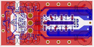
If I could make one remark? Avoid that blue signals "see" red signals: for example, the long blue line to gate resistors would be better going through the middle of the power resistors.
JP
JP
That was also an Idea to change the Transistors to SMD variants
But which types
Yes .. with 0402/0603 SMD parts of IS much smaller
But i would leave the components Like original.
Resistors are 1206 .. so quite big ..
Caps are FKP or MKP WIMA types.
X5R oder X7R are Not so good for audio.
NP0 types are quite expensive or only OK for very small values.
Red is bottom layer and blue ist top layer
Yes i will Post a Picture or PDF later...
Look for BC8xxW for SOT23 equivalent of BC5xx.
For the drivers, SOT223 DZT5401 is good for PNP and DZT5551 is NPN. $0.42ea, 160V, 600mA, 1W dissipation and a bizillion in stock. Really nice parts. I use as preamp or headphone amp output drivers.
For the drivers, SOT223 DZT5401 is good for PNP and DZT5551 is NPN. $0.42ea, 160V, 600mA, 1W dissipation and a bizillion in stock. Really nice parts. I use as preamp or headphone amp output drivers.
Last edited:
Yes.. bc856/846 .. or similar
Better would be a dual Part Like
BC846BPDW1..
5401 /5551 .. i will Check.
An additional Copper or Aluminium Part between heatsink and SMD Part on bottom Side for thermal coupling.
Or an Second PCB Like an PCB Module on PCB.
Depends on height of the 5401/5551 parts
For me .. Sounds Like a good Plan
Better would be a dual Part Like
BC846BPDW1..
5401 /5551 .. i will Check.
An additional Copper or Aluminium Part between heatsink and SMD Part on bottom Side for thermal coupling.
Or an Second PCB Like an PCB Module on PCB.
Depends on height of the 5401/5551 parts
For me .. Sounds Like a good Plan
Attachments
Last edited:
If you provide some copper planes (12mm x 15mm should do it) with vias around the SOT223's you can easily dissipate about 1W into the PCB itself. No need for thermal transfer block to the main heatsink. I forget how much power these drivers have but don't recall them getting that hot.
The dual matched SMT BJTs is a great idea.
The dual matched SMT BJTs is a great idea.
dual BC846BDW is still available ...
seems that is a very good replacement for typical 546/556
simulation is ok .. not optimized
too tired today ^^
see attached files... i hope .models are ok
replacement for BD139 is BCP56 ... but how to connect to heatsink...
PBHV8540/PBHV9040 are not so good ...
DZT5551/DZT5401 are ok ..
but not as good as KSA/KCS
PZTA42/PZTA92 ( MPSA SMD types )
i learned today:
these drivers are important for audio ...
Attachments
Last edited:
I would leave BD139 as is, as it serves as the temp sensor. No point on making it SMT.
KSA1381 and KSC3503 are getting hard to find.
I use DZT5401 in place of KSA1381 and find that it works great on Aksa Lender. Measures well too.
KSA1381 and KSC3503 are getting hard to find.
I use DZT5401 in place of KSA1381 and find that it works great on Aksa Lender. Measures well too.
I think the radial bulk metal power resistors you had before are fine (like KOA BPR series) It’s what I prefer since it can radiate heat and is very low distortion. You don’t want metal oxide film for MOSFET source resistors. They add third harmonic distortion. The SMTs also have to conduct heat to the PCB as heatsink.
Rest looks good. I agree Wima no caps are fine for bypass. Although power bypass with X7R 0.1uF 100v is really actually very good as they are low ESR. It’s audio path that I avoid X7R. Like compensation caps in the pF range then use NP0/C0G ceramic.
Rest looks good. I agree Wima no caps are fine for bypass. Although power bypass with X7R 0.1uF 100v is really actually very good as they are low ESR. It’s audio path that I avoid X7R. Like compensation caps in the pF range then use NP0/C0G ceramic.
Nice work Saddevil! I like the usage of the dual BJT transistor, stock might be an issue in these times though 🙁
I'd tend to agree with X about using radial/axial leaded source resistors instead of SMD's.
Maybe include a few voltage test point locations on the pcb to check bias current, post capMx voltage, etc..?

I'd tend to agree with X about using radial/axial leaded source resistors instead of SMD's.
Maybe include a few voltage test point locations on the pcb to check bias current, post capMx voltage, etc..?
I'm fighting with Layout
Parts on top are much better for gnd plane.
I can Put some x7R directly between Pins of Cap...
Parts on top are much better for gnd plane.
I can Put some x7R directly between Pins of Cap...
X7R's between pins of TH radial caps is exactly the way to do it. Don't be afraid to use an occasional wire jumper to solve layout problems. That's the advantage of through hole resistors - they provide a means for traces to cross over a longer distance.
- Home
- Amplifiers
- Solid State
- CFH7 Amp