Hi X,
From whom I could get (order) a pair PCB with the 2X power mosfets?
Looks like this is compatible with my good old Darlington with some different resistor values. 🙂 Would love to have a pair.
Greetings
From whom I could get (order) a pair PCB with the 2X power mosfets?
Looks like this is compatible with my good old Darlington with some different resistor values. 🙂 Would love to have a pair.
Greetings
Attachments
Last edited:
You can order directly from JLCPCB.com just upload the Gerber and select options likePCB thickness and copper thickness and ENIG if you like. Basic 1.6mm thick and if board is under 100mm x 100mm I think 5 boards is $2. Shipping another $15 to $22 for DHL.
I might get some (thinking about it still), in which case I’ll just send you a set! 🙂
Good to hear from you, btw. It’s been too long! How are you doing?
I might get some (thinking about it still), in which case I’ll just send you a set! 🙂
Good to hear from you, btw. It’s been too long! How are you doing?
Last edited:
Thank you!
I would like to do a A-B listening test between this and the orig Darlington.
I would like to do a A-B listening test between this and the orig Darlington.
Last edited:
Thanks for the corrections ��
I will play with ne new file ...
I have built new speakers ...
and my last Idea was to use a class d AMP based in tpa3255
Layout ist Here and running
But i will test a analog circuit too.
5 to 10 years ago i repaired some of my old car amplifiers.
I ordered Lots of IRFP240/9240 mosfets and Matched These.
Now i have about 12 good pairs..
So i searched for an amplifier with these mosfets
That ist the reason why i Play with this circruit.
8 pairs of 2SK1058 / 2SJ162 are also Here in my desk.
Last edited:
That is plan B ..
If this amp is Not working😀
Or what would you say
CFH9 or FH9 ...
Power is enough for both amps..
Speakers sensivity is about ~93dB
Is one type "better"... Or what are the difference in sounding ?
If this amp is Not working😀
Or what would you say
CFH9 or FH9 ...
Power is enough for both amps..
Speakers sensivity is about ~93dB
Is one type "better"... Or what are the difference in sounding ?
Last edited:
You can order directly from JLCPCB.com just upload the Gerber and select options likePCB thickness and copper thickness and ENIG if you like. Basic 1.6mm thick and if board is under 100mm x 100mm I think 5 boards is $2. Shipping another $15 to $22 for DHL.
I might get some (thinking about it still), in which case I’ll just send you a set! 🙂
Good to hear from you, btw. It’s been too long! How are you doing?
Thanks for your question about my health! Really appreciated!🙂
Not much better but I want to take of my focus only of the situation (do some (DIY) or something what interests. 🙂
I am familiar with these amp, you know that😉😉 reason I would love to do an AB test between the Hex-Fet and the Darlington version.
The Lateral sound much softer (to me to soft) at bass.
If you ever have an EXTRA pair of PCB I will pay for it and of course I will pay for the shipping to. By the way HOW would you rank this amp compare some others you built? I do not want to order from the factory, I have some bad experience with the Symasim PCB's i ordered way back (many years a go) from China.
Hi Gaborbela,
The FH9HVX is among one of the top 3 amps I have I think. It has been so long since i listened to the CFH9, but recall it sounded very nice as well. I would expect them to sound similar in the bass department as both are HEXFET complimentary output stages - but the CFA topology is probabbly more resolving, possibly lower distortion. But great sound is not all about ultiamate low distortion. I gave away my FH9HVX Griddle Amp to a good friend who is enjoying it immensely. So even if I built the CFH9 again, I cannot do a proper AB comparison.
What I will say is that if the FH9HVX was the last amp I built and all I had to listen to from here on out, I would not be unhappy. 🙂
Having said that, I will order some CFH9 PCBs (the Thiago ones with Cap Mx) and build them up and listen to it again. And I'll send you some PCB's - don't worry about paying me for the boards or shipping. It is the least I can do for the matched 2SK170's and 2SJ74's you gave me! It is hard though to find freee time for "hobby" projects as I have some commissioned projects that I need to finish up. A 100w Class A amp, being the big one.
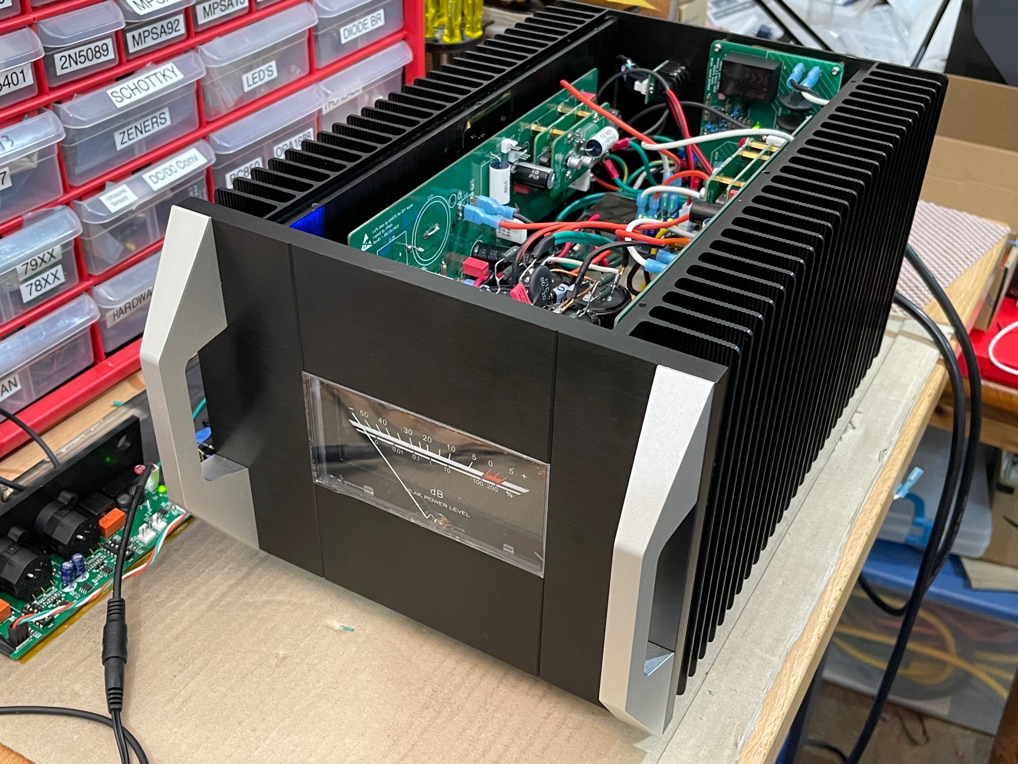
Griddle Amp:
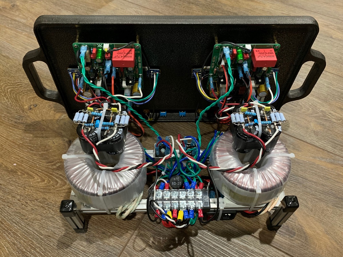
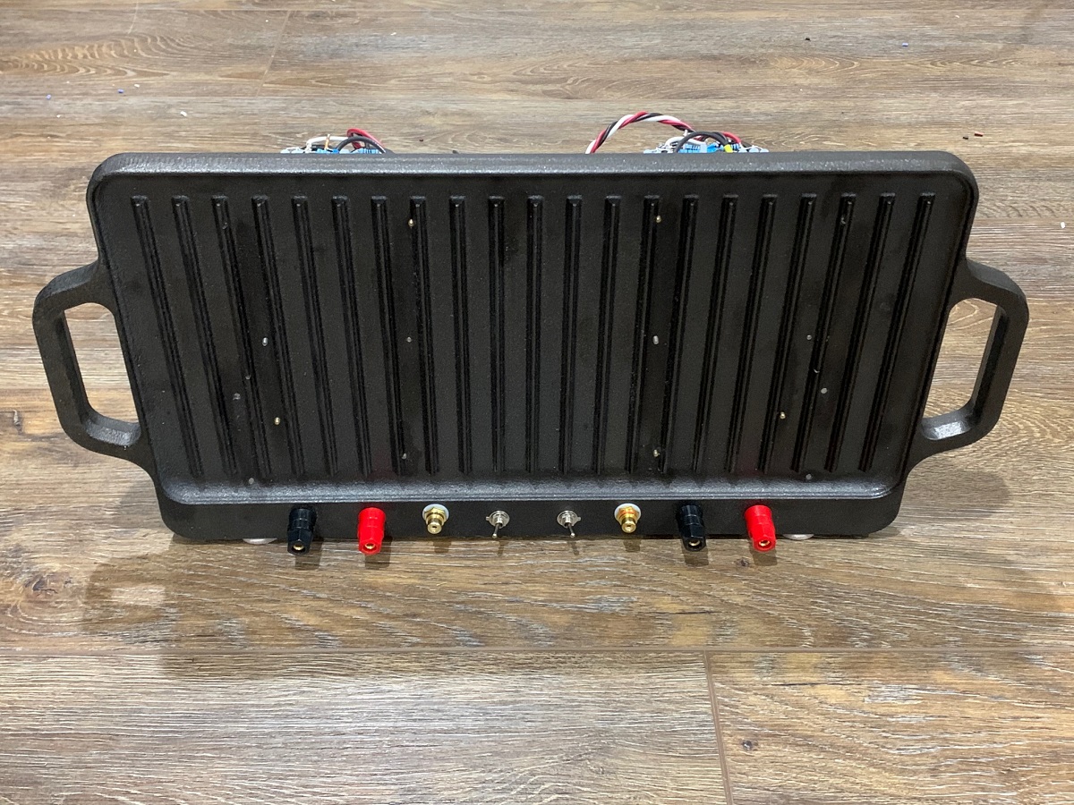
Here is the 100W Class A monoblock prototype. One channel completed, need to build second for stereo.
The FH9HVX is among one of the top 3 amps I have I think. It has been so long since i listened to the CFH9, but recall it sounded very nice as well. I would expect them to sound similar in the bass department as both are HEXFET complimentary output stages - but the CFA topology is probabbly more resolving, possibly lower distortion. But great sound is not all about ultiamate low distortion. I gave away my FH9HVX Griddle Amp to a good friend who is enjoying it immensely. So even if I built the CFH9 again, I cannot do a proper AB comparison.
What I will say is that if the FH9HVX was the last amp I built and all I had to listen to from here on out, I would not be unhappy. 🙂
Having said that, I will order some CFH9 PCBs (the Thiago ones with Cap Mx) and build them up and listen to it again. And I'll send you some PCB's - don't worry about paying me for the boards or shipping. It is the least I can do for the matched 2SK170's and 2SJ74's you gave me! It is hard though to find freee time for "hobby" projects as I have some commissioned projects that I need to finish up. A 100w Class A amp, being the big one.
Griddle Amp:
Here is the 100W Class A monoblock prototype. One channel completed, need to build second for stereo.
Last edited:
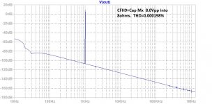
For comparison, here is LTspice prediction of CFH9 making 1W (8.0Vpp) into 8ohms - essentially distortion free.
I have ordered the PCBs:

Code:
Harmonic	Frequency	 Fourier 	Normalized	 Phase  	Normalized
 Number 	  [Hz]   	Component	 Component	[degree]	Phase [deg]
    1   	1.000e+03	4.060e+00	1.000e+00	   -0.08°	    0.00°
    2   	2.000e+03	4.982e-06	1.227e-06	  177.28°	  177.36°
    3   	3.000e+03	3.914e-06	9.640e-07	  169.33°	  169.41°
    4   	4.000e+03	2.926e-06	7.207e-07	 -179.92°	 -179.84°
    5   	5.000e+03	2.354e-06	5.797e-07	 -179.83°	 -179.75°
    6   	6.000e+03	1.960e-06	4.828e-07	 -179.96°	 -179.89°
    7   	7.000e+03	1.679e-06	4.135e-07	 -179.97°	 -179.89°
    8   	8.000e+03	1.468e-06	3.615e-07	 -179.97°	 -179.89°
    9   	9.000e+03	1.304e-06	3.211e-07	 -179.97°	 -179.89°
Total Harmonic Distortion: 0.000198%(0.000000%)
I have ordered the PCBs:
Attachments
Last edited:
i played a bit
at 68Vpp
at ~9Vpp
at 68Vpp
Harmonic Frequency Fourier Normalized Phase Normalized
Number [Hz] Component Component [degree] Phase [deg]
1 1.000e+03 3.445e+01 1.000e+00 -0.21° 0.00°
2 2.000e+03 1.093e-04 3.173e-06 19.56° 19.77°
3 3.000e+03 2.486e-04 7.216e-06 85.61° 85.82°
4 4.000e+03 7.736e-05 2.246e-06 172.90° 173.11°
5 5.000e+03 8.900e-05 2.584e-06 -98.50° -98.29°
6 6.000e+03 1.796e-05 5.212e-07 173.98° 174.19°
7 7.000e+03 3.135e-05 9.101e-07 93.00° 93.21°
8 8.000e+03 2.580e-05 7.490e-07 176.88° 177.09°
9 9.000e+03 7.296e-06 2.118e-07 113.79° 114.00°
Total Harmonic Distortion: 0.000869%(0.000000%)
at ~9Vpp
Harmonic Frequency Fourier Normalized Phase Normalized
Number [Hz] Component Component [degree] Phase [deg]
1 1.000e+03 4.388e+00 1.000e+00 -0.21° 0.00°
2 2.000e+03 7.413e-06 1.689e-06 154.82° 155.03°
3 3.000e+03 3.512e-06 8.002e-07 99.61° 99.82°
4 4.000e+03 1.118e-06 2.547e-07 -179.56° -179.35°
5 5.000e+03 8.974e-07 2.045e-07 165.86° 166.07°
6 6.000e+03 6.868e-07 1.565e-07 -179.31° -179.10°
7 7.000e+03 6.447e-07 1.469e-07 -178.82° -178.61°
8 8.000e+03 5.605e-07 1.277e-07 -179.97° -179.76°
9 9.000e+03 4.990e-07 1.137e-07 -179.75° -179.54°
Total Harmonic Distortion: 0.000192%(0.000000%)
What values were you adjusting? I had not played with bias current yet in the input or output stages yet.
That is combination of bias in Input Stage and Driver Stage bias
With adding a additional CM + Filter for Input/Driver stage connected to Main supply to avoid a massive voltage drop of 2CM in series
Input Stage is about 2mA
Driver stage is about 16mA ( this increases K2 a Bit )
With adding a additional CM + Filter for Input/Driver stage connected to Main supply to avoid a massive voltage drop of 2CM in series
Input Stage is about 2mA
Driver stage is about 16mA ( this increases K2 a Bit )
Last edited:
what do you think about a mixed mode amplifier
like described here:
https://www.diyaudio.com/forums/solid-state/922-technics-class-bias-circuits.html#post2232564
in short:
We need 2 amplifiers for one channel in this case ...
One part is running with low voltage in full class A.
The midpoint of this low voltage is connected to output of the second amplifier.
This secondary amplifier is running in Class B .. or AB.
the class A is running at low voltage and "low" heat dissipation.
the class B drives the voltage
that "should" be resulting in a Class A sounding with Class B/AB dissipation.
i will try to simulate this strange construct ...
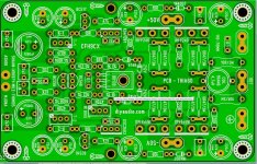
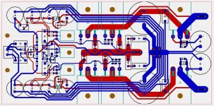
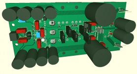
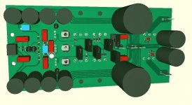
in meantime i finished the layout for CFH9 + CMx
160 x 78mm for one complete channel
some parts have a wrong 3D drawings ... it is too much work for corrections ^^
like described here:
https://www.diyaudio.com/forums/solid-state/922-technics-class-bias-circuits.html#post2232564
in short:
We need 2 amplifiers for one channel in this case ...
One part is running with low voltage in full class A.
The midpoint of this low voltage is connected to output of the second amplifier.
This secondary amplifier is running in Class B .. or AB.
the class A is running at low voltage and "low" heat dissipation.
the class B drives the voltage
that "should" be resulting in a Class A sounding with Class B/AB dissipation.
i will try to simulate this strange construct ...
in meantime i finished the layout for CFH9 + CMx
160 x 78mm for one complete channel
some parts have a wrong 3D drawings ... it is too much work for corrections ^^
Attachments
Last edited:
I didn’t realize you were adding a high current cap Mx to the main outputs. This is a Class AB amp with reasonable PSRR so should not need a cap Mx on output stage which limits max current for deep bass transients. You will also lose 4v drop per rail or 8v total of peak to peak and this is a lot of power loss. You can compensate with a linear trafo that is rated higher voltage. But in general, I only use cap Mx on output stage for Class A amps that have lower PSRR.
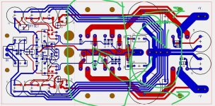
On your layout, you have a lot of long ground traces that go past high current regions. This creates a large loop cross sectional area that might pick up emitted EMI from high currents. Perhaps use a ground plane on one side of PCB? Or place ground star hub more central to minimize the length of the spokes from the star hub.
On your layout, you have a lot of long ground traces that go past high current regions. This creates a large loop cross sectional area that might pick up emitted EMI from high currents. Perhaps use a ground plane on one side of PCB? Or place ground star hub more central to minimize the length of the spokes from the star hub.
I didn’t realize you were adding a high current cap Mx to the main outputs. This is a Class AB amp with reasonable PSRR so should not need a cap Mx on output stage which limits max current for deep bass transients. You will also lose 4v drop per rail or 8v total of peak to peak and this is a lot of power loss. You can compensate with a linear trafo that is rated higher voltage. But in general, I only use cap Mx on output stage for Class A amps that have lower PSRR.
Yes - 🙁
it is better to have them than to need them , or?
i can remove the Fets and bridge the pins
question is: is this a real problem or can it be a benefit
usecase is normal listening ... no full power use
speakers have a good sensivity, so i dont need so much power
so idea is to have better PSRR , SNR and channel separation
On your layout, you have a lot of long ground traces that go past high current regions. This creates a large loop cross sectional area that might pick up emitted EMI from high currents. Perhaps use a ground plane on one side of PCB? Or place ground star hub more central to minimize the length of the spokes from the star hub.
yes .. i know .... :-(
one option is to place an additional GND connector as second ground star for input
second is to use one very large GND trace instead of the 4 smaler traces
nearly a large plane on top side
Move the ground more to the input side makes pcb larger ( no option )
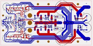
Here is how I would approach it. Swap the output stage cluster with the ground star hub cluster. Please see sketch markup. Use thick ground trace rather than many smaller equal length ones to reduce EMI pickup and rely on low impedance path. This centralizes the star hub to board centroid. I recall Thimios had oscillations when bulk rail caps were large 4700uF and switching to 100uF stopped oscillation. Make the caps after the cap Mx smaller. Probably 1000uF max. Cap Mx would decrease ripple by about 50dB but loss of 4v is too much of a tradeoff in my mind.
I would also move the actives out closer to the edge so bolts visible without cutout holes. Lining all that up and precisely tapping 7 holes on heatsink will be a pain.

I would also move the actives out closer to the edge so bolts visible without cutout holes. Lining all that up and precisely tapping 7 holes on heatsink will be a pain.
Attachments
- Home
- Amplifiers
- Solid State
- CFH7 Amp