At the moment i will try to find a Solid solution with bc846/bc856 and dzt5551/5401 Simulation.
But it is hard to get the same good results
K3 ist higher than before.
But it is hard to get the same good results
K3 ist higher than before.
The models might not be that accurate. I think the topology is going to affect the harmonic profile more than the actives. This CFA front end topology is inherently dominant third harmonic. But that assumes perfect matching of the N and P sides. In reality they are not and so overall THD will be higher along with the more desirable second harmonic. I think all we can do is build test and listen at this point. If you wanted to induce some more H2 make the source resistors asymmetric. 0.15ohm and 0.22ohm for example.
i tested something but i can't reduce THD down to THT variant with BC546/556;KSA/KSC types
tested also a completely different input ...
see .asc file
but it does not help
so i will attach the first version of THT variant include Gerber
see .zip
tested also a completely different input ...
see .asc file
but it does not help
so i will attach the first version of THT variant include Gerber
see .zip
Attachments
Last edited:
You can build the board with optional TH pads for those that want to try regular TO92 and TO126 actives. Doesn’t take up too much room as there is plenty of space on the PCB. One board for both. I would label components generically rather than actual value. That leaves the chance for adjustments or error corrections in BOM part values. I do like convenience is stuffing a part without looking at a schematic and spreadsheet though.
input is very easy 😀
that is a very good idea
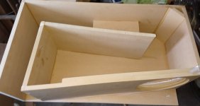
TO126 ... is a bit more complex
one idea is like the picture
but then i have to add a alu/cooper parts between drivers and heatsink
But then you can also use BCP56 instead of BD139
Back to Ltspice :
i'm playing with SMD variant and with less current in input stage( ~1,6-1,8mA)
@ typical 68 Vpp
and also 9Vpp
that is a very good idea
TO126 ... is a bit more complex
one idea is like the picture
but then i have to add a alu/cooper parts between drivers and heatsink
But then you can also use BCP56 instead of BD139
Back to Ltspice :
i'm playing with SMD variant and with less current in input stage( ~1,6-1,8mA)
@ typical 68 Vpp
it is nearly similar to BC556/KSC variant
Harmonic Frequency Fourier Normalized Phase Normalized
Number [Hz] Component Component [degree] Phase [deg]
1 1.000e+03 3.444e+01 1.000e+00 -0.13° 0.00°
2 2.000e+03 3.079e-04 8.940e-06 -96.95° -96.82°
3 3.000e+03 3.056e-04 8.871e-06 81.06° 81.18°
4 4.000e+03 5.917e-05 1.718e-06 177.05° 177.18°
5 5.000e+03 9.764e-05 2.835e-06 -95.13° -95.00°
6 6.000e+03 3.120e-05 9.059e-07 -176.98° -176.85°
7 7.000e+03 1.831e-05 5.315e-07 103.50° 103.62°
8 8.000e+03 2.736e-05 7.944e-07 -175.66° -175.53°
9 9.000e+03 9.386e-06 2.725e-07 113.80° 113.93°
Total Harmonic Distortion: 0.001309%(0.000000%)
28K | 680R | 15R
and also 9Vpp
Harmonic Frequency Fourier Normalized Phase Normalized
Number [Hz] Component Component [degree] Phase [deg]
1 1.000e+03 4.386e+00 1.000e+00 -0.12° 0.00°
2 2.000e+03 1.114e-05 2.540e-06 -162.95° -162.83°
3 3.000e+03 1.534e-06 3.498e-07 136.12° 136.24°
4 4.000e+03 1.807e-06 4.119e-07 176.41° 176.53°
5 5.000e+03 9.182e-07 2.094e-07 159.43° 159.55°
6 6.000e+03 7.400e-07 1.687e-07 -179.93° -179.80°
7 7.000e+03 6.393e-07 1.458e-07 177.65° 177.78°
8 8.000e+03 5.509e-07 1.256e-07 -179.98° -179.86°
9 9.000e+03 4.949e-07 1.128e-07 -179.99° -179.87°
Total Harmonic Distortion: 0.000262%(0.000000%)
Attachments
Last edited:
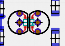
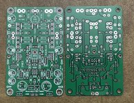
first impressions of dual layout
SOT223 pin"4" is output of driver to gates
but at the moment i doesn't have an idea how to place ...
i will change the LED to SMD .. but this is important for resistor values for bias
so i will find a good red led with nearly stable Vfwd
SOT223 pin"4" is output of driver to gates
but at the moment i doesn't have an idea how to place ...
i will change the LED to SMD .. but this is important for resistor values for bias
so i will find a good red led with nearly stable Vfwd
Attachments
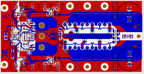
Nice use of tab (pin 2) for heat sink! I like it. That is about the right amout of copper for transfering the heat out of the SOT223. If you wanted to double it, make an identical plane on the bottom and connect with a bunch of vias. Isolated from ground plane of course.
I think i will use a smaller Pad with vias
In bottom Side there ist GND plane.
And i won't use 4layer PCB 😁
I will Doublecheck footprints and searching for suitable parts
Including a list.. (digikey/mouser)
But then i will Order parts.
So i have Something to do between 26.12. and 31.12 😁
Speakers are waiting of an amplifier....
In bottom Side there ist GND plane.
And i won't use 4layer PCB 😁
I will Doublecheck footprints and searching for suitable parts
Including a list.. (digikey/mouser)
But then i will Order parts.
So i have Something to do between 26.12. and 31.12 😁
Speakers are waiting of an amplifier....
Attachments
transfering .. yes . not so good as it is directly connected.
but in this way GND plane is only perforated ....
One negative Part of this is the capacity at the Gate drivers.
This Planes Creating a Cap.
but in this way GND plane is only perforated ....
One negative Part of this is the capacity at the Gate drivers.
This Planes Creating a Cap.
Attachments
Last edited:
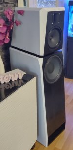
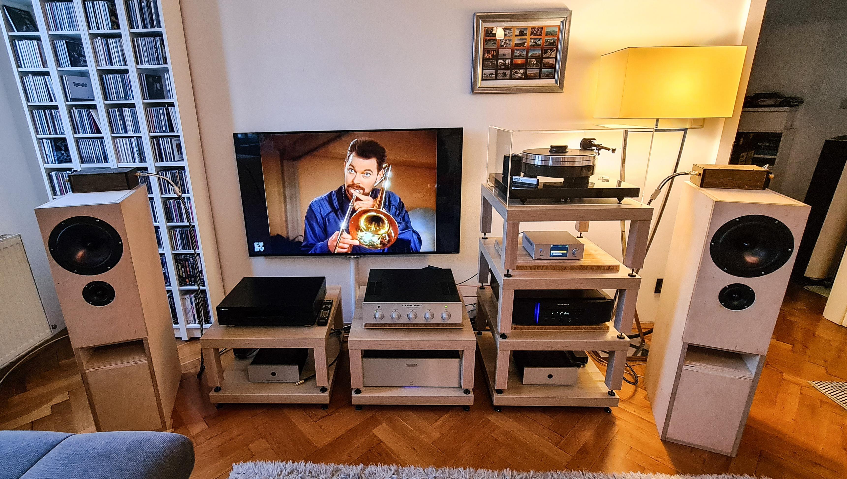
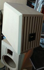
Nice speakers! That looks like a TL on the woofer and a horn loaded ribbon. What speaker design is this or your own?
If you need an amp to try quickly, the 100w FH9HVX is excellent. PCBs available right away.
If you need an amp to try quickly, the 100w FH9HVX is excellent. PCBs available right away.
Speakers are
Fountek Neo CD3.5H
Visaton BG20 modified
In a damped Open baffle
Back part is open Like a large variovent
Eminence Legend BP102 in a 2.1m TML
Design ist my own .. or i doesn't know If somewere build this in this way ��
Actually i'm using a China TPA3255 to Power the speakers.
Fountek Neo CD3.5H
Visaton BG20 modified
In a damped Open baffle
Back part is open Like a large variovent
Eminence Legend BP102 in a 2.1m TML
Design ist my own .. or i doesn't know If somewere build this in this way ��
Actually i'm using a China TPA3255 to Power the speakers.
I like TLs a lot but never considered the BP102 for a driver. Do you have simulations of the TL design? I am curious what the bass extension is. Most pro audio woofers like Legend don’t go that low. Highly sensitive though.
I have RS225-8 in a TL at present and it sounds superb. Using ScanSpeak 10F for midrange and highs.
More here:
10F/8424 & RS225-8 FAST / WAW Ref Monitor
Some variants possible with B80 as midtweeter like latest one by member Plott:
I have RS225-8 in a TL at present and it sounds superb. Using ScanSpeak 10F for midrange and highs.
More here:
10F/8424 & RS225-8 FAST / WAW Ref Monitor
Some variants possible with B80 as midtweeter like latest one by member Plott:
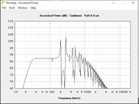
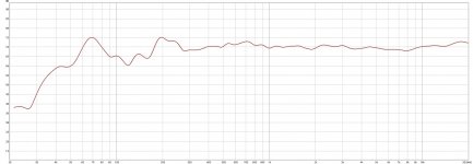
BP102 has a Fres of ~35Hz
EDIT: attached measurement ...
in room of about 1m distance
EDIT: attached measurement ...
in room of about 1m distance
Attachments
Last edited:
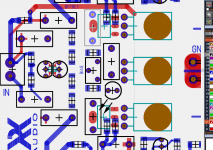
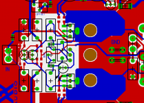
updated version with dual parts ... THT and SMD
i will order 5 PCBs 🙂
i will order 5 PCBs 🙂
Attachments
Nice work!
Question on schematic is why there are 22v Zener diodes on the front end rails? Was this meant to be a voltage regulator? It should be quiet (from cap Mx) but float up and down with the rails to allow relative operation over different rail voltages. The front end tends to need more voltage than the output stage if you wanted to give it its own PSU. I also see 6.3v rated caps on the front end.
Question on schematic is why there are 22v Zener diodes on the front end rails? Was this meant to be a voltage regulator? It should be quiet (from cap Mx) but float up and down with the rails to allow relative operation over different rail voltages. The front end tends to need more voltage than the output stage if you wanted to give it its own PSU. I also see 6.3v rated caps on the front end.
yes
simulate it with different main supply voltage
problem is ... the current on input ( of about 1,8mA ) depends on main voltage
small changes on main supply resulting in small changes on the input current
and finally in large changes in VAS stage
this 22V zener is a bit more DIY friendly and more stable in this part
BIAS is a bit more stable between 40-55V supply voltage with this 22V zener
and with the 12Kohm resistor it is still quiet enough
on other hand .. if you don't want to use the Zener , you don't place it and use correct values for resistors ( ~24-28kOhm @50V )
voltage @ 2200µF is nearly the Vbe voltage
Last edited:
- Home
- Amplifiers
- Solid State
- CFH7 Amp