If a clipping indicator is developed which trips on distortion level (error level) ..... several lights/LED can show... 0.1%, 1%, 10% levels of clipping affect.
THx-RNMarsh
THx-RNMarsh
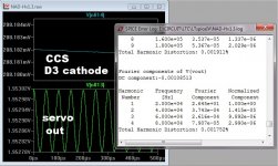
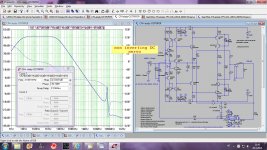
This is the corresponding data part to Dvorak2.png image in my previous post.
PMA, like the case of a single dropped sample in a piece of music, I have a hard time attributing a "sound" to an isolated clipping event in a very loud passage.
This is not about how much clipping can one hear or can stand to hear. not about same re. compression either. This is about perfecting the designs and listening environment... including the electronics. Not into how much compromise can one stand to have. That is another subject for elsewhere.
THx-RNMarsh
THx-RNMarsh
Last edited:
I have provided a real transient signal capture, worst case for my system, with 6dB reserve to amplifier clipping - nothing about compromises.
Good.... general comment- reflex- when anyone talks about hearing or not hearing anything.
Clipping and limiting and compression occures on a regular basis in recordings..... including digital recordings.
What was the venue volume/size? Listening distance? And, if the speakers were 6 dB less efficient... what would your power amp be rated, then?
THx-RNMarsh
Clipping and limiting and compression occures on a regular basis in recordings..... including digital recordings.
What was the venue volume/size? Listening distance? And, if the speakers were 6 dB less efficient... what would your power amp be rated, then?
THx-RNMarsh
Last edited:
............... And, if the speakers were 6 dB less efficient... what would your power amp be rated, then?
THx-RNMarsh
We both know the answers very well.
Its not for me... for the readership here.... many follow along without comment (254,000 views). And, it relates to the power needed to prevent clipping... another independent data point.
THx-RNMarsh
THx-RNMarsh
Last edited:
In the "trench"
Wow... 😱 A lot of views.
Yes , we need power. And a front end that is stable (in all ways).
(below) Is the next best thing. The "last best thing" works very
good ... (the NX/NAD). Many have built it.
I just can't leave it be 😀 ...
-more PSRR
-better offset
-lower THD
-keep it simple
I seem to have succeeded. Keep seeing these ideas in other threads -
but that's cool....
Member Dadod has me beat by a few PPM - but his ideas are
very good ("ditch" the diamond 😀).
OS
Attachments
Yes , we need power. And a front end that is stable (in all ways).
(below) Is the next best thing. The "last best thing" works very
good ... (the NX/NAD). Many have built it.
I just can't leave it be 😀 ...
-more PSRR
-better offset
-lower THD
-keep it simple
OS
This is engineering at its best.... the interaction of the members to give and get ideas, concepts and challenged to improve further.
Now we are into the Simplified CMA/CFA.
😎🙂😀: cheers:
THx-RNMarsh
Last edited:
Wow... 😱 A lot of views.
Yes , we need power. And a front end that is stable (in all ways).
(below) Is the next best thing. The "last best thing" works very
good ... (the NX/NAD). Many have built it.
I just can't leave it be 😀 ...
-more PSRR
-better offset
-lower THD
-keep it simple
I seem to have succeeded. Keep seeing these ideas in other threads -
but that's cool....
Member Dadod has me beat by a few PPM - but his ideas are
very good ("ditch" the diamond 😀).
OS
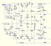
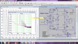
OS, I think that you did two errors with your DC servo here, first you should use non inverting servo, second increase DC servo output resistor, try 220k. Try to plot LG with your DC servo and then with suggested changes.
Dado
OS, I think that you did two errors with your DC servo here, first you should use non inverting servo, second increase DC servo output resistor, try 220k. Try to plot LG with your DC servo and then with suggested changes.
Dado
Non- inverting gives me -20v offset ! 220k works , but requires the servo
to output 8V for correction. 47k only 1V.
It works (below) as posted.
PS - I'm using 12V supplies and no cascodes. Output has -4V offset with
no servo ... so the servo is "servoing" 😀 .
OS
Attachments
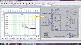
Another thing that worries me about "ditch the diamond" ...
is the very low Vceo of the input pair and the saturation
characteristics at these voltages.
I only gain a few PPM over the diamond IP stages THD and
LOSE 3+ db CLG. 😕
UG + bandwidth and slew are constant (very close), either way ... as well.
But it works , and works good ... either way .
OS
is the very low Vceo of the input pair and the saturation
characteristics at these voltages.
I only gain a few PPM over the diamond IP stages THD and
LOSE 3+ db CLG. 😕
UG + bandwidth and slew are constant (very close), either way ... as well.
But it works , and works good ... either way .
OS
Non- inverting gives me -20v offset ! 220k works , but requires the servo
to output 8V for correction. 47k only 1V.
It works (below) as posted.
PS - I'm using 12V supplies and no cascodes. Output has -4V offset with
no servo ... so the servo is "servoing" 😀 .
OS
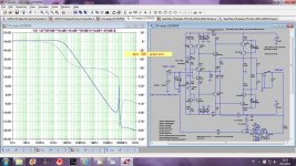
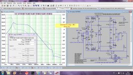
Because what you said above I simulated your IPS in isolation with inverting and non inverting DC servo. I used different transistors all models from Cordell. I don't understand how did you get -20V offset, and even -4V offset with no DC servo is to much. I got -130mV offset in my simulation with no DC servo connected.
In my simulation both kind of the DC servo works bur with inverting servo distortion rises specially at low frequencies.
Tell me what I do wrongly here??
Damir
Attachments
One issue we never seemed to get to is ---
As soon as it was learned the classic CMA(CFA) was a slew rate beast, an effort went into making VFA have faster SR, also. And, to make CMA/CFA have lower thd. So that basically both topologies could have similar performance numbers -- . So, the question that remains, in my mind, is this -- does the standard of .5 to 1v/usec sound the same as a 200-300v/usec or more amplifier - both with super low thd, same power etc. And, is there a new threshold to use for SR? If so, what would it be for a min spec?
THx-RNMarsh
Last edited:
One issue we never seemed to get to is ---
As soon as it was learned the classic CMA(CFA) was a slew rate beast, an effort went into making VFA have faster SR, also. And, to make CMA/CFA have lower thd. So that basically both topologies could have similar performance numbers -- . So, the question that remains, in my mind, is this -- does the standard of .5 to 1v/usec sound the same as a 200-300v/usec or more amplifier - both with super low thd, same power etc. And, is there a new threshold to use for SR? If so, what would it be for a min spec?
THx-RNMarsh
I'm inclined to say that 50V/us is plenty for a 100W amplifier, and scale up from there for higher-power amplifiers.
My MOSFET EC amp was a VFA of only 50 watts, yet had a slew rate of 300V/us. It employed MIC compensation with a 2MHz global ULGF.
Cheers,
Bob
I also thought of this ... what traits would a "slow" CFA have ?
This would be hard(er) , to make a CFA with low SR is as hard as
making a VFA with high SR.
Perhaps a comparison of a Valve (tube) amp would be a more
likely choice.
OS
This would be hard(er) , to make a CFA with low SR is as hard as
making a VFA with high SR.
Perhaps a comparison of a Valve (tube) amp would be a more
likely choice.
OS
Does anyone remember this neglected old thread?
http://www.diyaudio.com/forums/solid-state/223202-alternativ-symmetric-amp.html
It's got indefinite drive or current on-demand. It's fully cascode-buffered which is one big reason for it's performance. Just be sure to consider thermal effects while simulating, so your real-life bias matches better.
Perhaps OS can make an amp for it?
I'm inclined to say that 50V/us is plenty for a 100W amplifier, and scale up from there for higher-power amplifiers.
My MOSFET EC amp was a VFA of only 50 watts, yet had a slew rate of 300V/us. It employed MIC compensation with a 2MHz global ULGF.
Cheers,
Bob
What would you have if that same amp design ended up with 50V/usec?
In other words, you got 300v/usec to get the results you were looking for... but still think 50 would do?!
How does that compute?
-RNM
Last edited:
- Home
- Amplifiers
- Solid State
- CFA Topology Audio Amplifiers