A clipping indicator is too little too late IMO
Because,all THX recordings are digital these days and therefore hard limited.
No, this amplifier is for audiophile usage. I just happens that the circuit design is based on some circuits patented by THX. It has nothing to do with THX program material. Moreover, whether an amplifier design incorporates a clip indicator has nothing to do with whether its circuit originated with the THX folks. My point is that it would be nice if other amplifier manufacturers had the stones to incorporate a clip indicator. I think people would learn a lot if their amplifiers made an indication when they clipped. For those who strongly assert that clipping does not happen, then light won't come on and they will not be bothered.
That said, a clipping indicator does add cost, and there are different ways to implement it.
Cheers,
Bob
Well said Bob. I can confirm this from personal experience.I think people would learn a lot if their amplifiers made an indication when they clipped. For those who strongly assert that clipping does not happen, then light won't come on and they will not be bothered.
I want these as well ... I would integrate them into the
protection circuit. Occasional clipping - indication .... sustained
hard clipping to a pre-set level ... cut the rails (latching reset)!
BTW - instead of having a SS relay in the signal path , cutting
the "juice" to the amps seems to be as good (or better) for
overload/DC/short protection. Single devices on the rails -
easy to implement , as well.
OS
@ ostripper
Re Post #5265
Yes & yes 🙂
I mentioned a very good & very simple clip indicator idea earlier on. It was one that JLH designed in the 80's in WW or ETI. One OpAmp & about 4 or 5 resistors plus LED. It compared the + - Amp inputs using the OpAmp, & any deviation showed clipping 😉
Re Post #5265
Yes & yes 🙂
I mentioned a very good & very simple clip indicator idea earlier on. It was one that JLH designed in the 80's in WW or ETI. One OpAmp & about 4 or 5 resistors plus LED. It compared the + - Amp inputs using the OpAmp, & any deviation showed clipping 😉
I don't think JLH was the first to suggest this very simple idea.I mentioned a very good & very simple clip indicator idea earlier on. It was one that JLH designed in the 80's in WW or ETI. One OpAmp & about 4 or 5 resistors plus LED. It compared the + - Amp inputs using the OpAmp, & any deviation showed clipping 😉
Got a link to his circuit?
Here's a rather better version http://sound.westhost.com/project57.htm#top
I would want to have some sort of 'hold' circuit leaving the LED on for about 2 secs. even after very short overloads.
@ kgrlee
Hi, yeah i also linked to that in my earlier post 😉 It is more advanced than JLH's, but the principle is the same. Simple yet Very effective = 🙂 He might not have been the 1st, but it was new to me @ the time.
I did try a www search for the JLH circuit, but didn't manage to locate it ? I do have the original in one of those mags saved "somewhere" If i can dig it out i'll scan & post it.
That would be fairly straightforward to accomplish 😉
***************
If there's going to be a DC cutoff in the event of faults, a soft start could be incorporated with it 🙂
Hi, yeah i also linked to that in my earlier post 😉 It is more advanced than JLH's, but the principle is the same. Simple yet Very effective = 🙂 He might not have been the 1st, but it was new to me @ the time.
I did try a www search for the JLH circuit, but didn't manage to locate it ? I do have the original in one of those mags saved "somewhere" If i can dig it out i'll scan & post it.
I would want to have some sort of 'hold' circuit leaving the LED on for about 2 secs. even after very short overloads.
That would be fairly straightforward to accomplish 😉
***************
If there's going to be a DC cutoff in the event of faults, a soft start could be incorporated with it 🙂
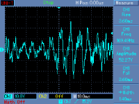
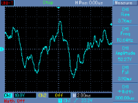
Digitizing scope + single shot trigger with properly set trigger level tell us if we are in clipping or not. Much more reliable than any circuit based indicator. The result is above any debates.
... i also linked to that in my earlier post 😉 It is more advanced than JLH's, but the principle is the same ...
I could not find those posts, could you provide a link ?
Presumably, you intend to supply this to all users of your amps 🙂Digitizing scope + single shot trigger with properly set trigger level tell us if we are in clipping or not. Much more reliable than any circuit based indicator. The result is above any debates.
After all, the idea of the clipping indicator is for the washed & unwashed masses to see while listening to music .. not while looking at stuff in the lab.
You got a condition where Rod Elliot's circuit won't show overload .. or indeed any type of misbehaviour .. including current limiting, oscillation etc ?
If you don't set your 'single shot trigger' properly, your solution may not show certain types of overload or misbehaviou. Rod's circuit triggers when the amp misbehaves.
Last edited:
@ gk7
I can't find it now either ! It "might" have been in another thread ? Anyway what i posted was more or the less the same info. The link was to ESP SIM (Sound Impairment Monitor) as kgrlee posted 😉
I can't find it now either ! It "might" have been in another thread ? Anyway what i posted was more or the less the same info. The link was to ESP SIM (Sound Impairment Monitor) as kgrlee posted 😉
Presumably, you intend to supply this to all users of your amps 🙂
After all, the idea of the clipping indicator is for the washed & unwashed masses to see while listening to music .. not while looking at stuff in the lab.
[/B]
Hopefully, I do not sell power amplifiers, except for some 3 - 4 pieces in the past.
I can provide you with a real life example from my listening conditions. I like to do it, I do not like to continue in empty debates.
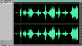
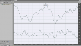
It is the most 'dynamic' track I have. Dvorak Symphony No.9, first movement, Adagio, time about 0:59. Telarc CD-80238, Previn, LA Orchestra. From nothing (very silent sound), there is a drum hit at full scale (digital full scale). My speakers sensitivity is about 89dB/2.83V/m. Please find time analysis of the music used, peak red circled. Attached is also a single shot measurement of the peak at a maximum sound level my ears are able to tolerate. Vp-p 52.27V is 6dB below amplifier clipping. Soon after drum hits I must turn the volume down, for the reason that following programme has much higher average sound level.
This is nothing against clipping indicators, just mentioning that things may get controlled very well.
Attachments
Last edited:
... The link was to ESP SIM (Sound Impairment Monitor)...
Thanks. This one requires a differential input stage though, and this is the CFA thread ...
I don't think JLH was the first to suggest this very simple idea.
Got a link to his circuit?
Here's a rather better version http://sound.westhost.com/project57.htm#top
I would want to have some sort of 'hold' circuit leaving the LED on for about 2 secs. even after very short overloads.
Here (the ESP circuit) , you would have to build this in
(or add a connector to the IPS).
Having those high -Z LTP bases running off on 2 wires (going to some
sensing circuit) is not appealing !
If you just compare the main OPS output (divided by it's global gain)
with the input ... it seems you could use the output to indicate ,
(in real time) a clipping event.
Going one step further , this same indicator could be averaged for
both sustained overload and a DC event.
One dual op-amp for these thresholds ... but you would need
additional circuitry to monitor the OP Re's (short circuit) 🙁 .
OS
Hi Guys
"Having those high -Z LTP bases running off on 2 wires (going to some
sensing circuit) is not appealing"
That is why isolation Rs are placed right at the diff amp and are usually 22k each or higher. Then there is no problem with stray capacitance etc. effecting the amp's performance. Bryston has similar circuitry built into all their amps.
Rod has another circuit that monitors the voltage across the output devices to show when they approach saturation. Monitoring the diff amp is more reliable and is all small-signal stuff - two buffers feeding a diff-amp, then into a rectifier and/or comparator. The output can be averaged or stretched however you wish and used simply for indication, or put to use to actually reduce the input signal and eliminate clipping. Where the output monitor only detects specific kinds of distortion, the input monitor can detect all distortions that the input stage is trying to correct.
Have fun
Kevin O'Connor
Last edited:
MiiB (5210)
I wonder why we keep on making global feedback amplifiers, this course (the CFA thread) has made it clear that the injection of feedback has to be done over less and fewer components,
Is it really necessary to use an input stage to correct errors that are primarily occurring in the OPS
I absolutely agree with you. Voltage amplifier (VAS) can be done with small nonlinear distortion using only local feedbacks
Power dissipation amplifying transistors Q1, Q2, Q6, Q10 is constant and equal to 13 mW, and thereby minimize heat (memory) distortion.
 [/URL][/IMG]
best regards
Petr
I wonder why we keep on making global feedback amplifiers, this course (the CFA thread) has made it clear that the injection of feedback has to be done over less and fewer components,
Is it really necessary to use an input stage to correct errors that are primarily occurring in the OPS
I absolutely agree with you. Voltage amplifier (VAS) can be done with small nonlinear distortion using only local feedbacks
Power dissipation amplifying transistors Q1, Q2, Q6, Q10 is constant and equal to 13 mW, and thereby minimize heat (memory) distortion.
best regards
Petr
That is why isolation Rs are placed right at the diff amp and are usually 22k each or higher. Then there is no problem with stray capacitance etc. effecting the amp's performance. Bryston has similar circuitry built into all their amps.
Still questionable.
MiiB (5210)
I wonder why we keep on making global feedback amplifiers, this course (the CFA thread) has made it clear that the injection of feedback has to be done over less and fewer components,
Is it really necessary to use an input stage to correct errors that are primarily occurring in the OPS
I absolutely agree with you. Voltage amplifier (VAS) can be done with small nonlinear distortion using only local feedbacks
Power dissipation amplifying transistors Q1, Q2, Q6, Q10 is constant and equal to 13 mW, and thereby minimize heat (memory) distortion.
[/URL][/IMG]
best regards
Petr
😎🙂
the CFA thread) has made it clear that the injection of feedback has to be done over less and fewer components
missed it
- Home
- Amplifiers
- Solid State
- CFA Topology Audio Amplifiers