Originally Posted by Bob Cordell
I'm inclined to say that 50V/us is plenty for a 100W amplifier, and scale up from there for higher-power amplifiers.
Depending on load, it will be more than the often recognised .5 V/us per output V. So "should" be quite acceptable 😉
If only scaling up was actually achieved with HPA's In my experience, most if not ALL so called pro HP Amps - 500W - 20,000W etc - fail miserabily, by a LONG way. Most are between 20 - 50 V/us & 100 is considered exceptional !
How many people here have been to any nightclubs/discos/concerts etc recently, or in the last say 10 years ? They can have between 50,000 - 500,000W, sometimes more for outdoors. But setup etc correctly & with HQ speakers, they can sound very pleasing. "Maybe" the inevitable distortions associated with pumping out such vast SPL's, mask the SR limitations ? I think they must.
Originally Posted by grhughes
The good doctor Leach (GA TECH) told me that the slew rate of an amp is set at the input.
Yes ! If an Amp etc has an input filter, which a lot have, that dictates the HF fr & SR. So even if an Amp has an Internal SR of a gazillion V/us it's limited by the input filter 😀
WOW !! 😱
Where did they get that IPS ?? (below)
Its "smokin' " fast and very easy to work with.
It's VFA .... but I could make it CFA 😀 try em' both....
OS

This is an 'H' bridge IPS.
Since the feedback signal is buffered, you can get very fast slew rates and settling time. Usually, there is a resistor between the two diamond stages, and this ultimately sets the slew rate.
This is an 'H' bridge IPS.
Since the feedback signal is buffered, you can get very fast slew rates and settling time. Usually, there is a resistor between the two diamond stages, and this ultimately sets the slew rate.
I had time to do the "9 yards" on this design.
I did put the resistor between the diamonds (out of desperation).
For some reason there is "peaking" at a few Mhz (above UG). Even as I get the
proper PM at UG , the SW will still ring when I trim the compensation. 🙁
I even tried lag/lead and shunt comp. techniques ... to no avail.
I suppose for a diamond , current FB is the way to go.

OS
I have not played extensively with it yet OS - you are well ahead of me there. I think you absolutely will need the resistor for it to be stable.
My guess is you can reduce the FB resistor to the value you would normally associate with the lower resistor in the feedback network.
If you are getting peaking it might be because you are inserting a pole in the FB network. A bit of MC might tame it.
Looking forward to you findings.
My guess is you can reduce the FB resistor to the value you would normally associate with the lower resistor in the feedback network.
If you are getting peaking it might be because you are inserting a pole in the FB network. A bit of MC might tame it.
Looking forward to you findings.
I have not played extensively with it yet OS - you are well ahead of me there. I think you absolutely will need the resistor for it to be stable.
My guess is you can reduce the FB resistor to the value you would normally associate with the lower resistor in the feedback network.
If you are getting peaking it might be because you are inserting a pole in the FB network. A bit of MC might tame it.
Looking forward to you findings.
I have it stable ... but at sub CFA slew. It also "does not like" the
Hawksford. It's greater gain (80+db) "irritates" the local FB hawksford
loop.
Going to the basic 2 device VAS makes for a stable setup .... STILL ,
it can't come close to either the Leach or NX.
Bottom line ... I can get it to do PPM , run stable , 100V/us slew ...
but it can't match the basic VSSA/NX speed. Diminishing returns 🙁 .
I won't go over a 14-16 device IPS - nobody will build it ... 😀
OS
Ostrpper, reason I asked was the desire to make a CFB balanced to single ended converter both as an IPS, and also for a line level circuit block
Ostrpper, reason I asked was the desire to make a CFB balanced to single ended converter both as an IPS, and also for a line level circuit block
There it is ... below.
OS
Attachments
This is an invention of mine. I have not seen a circuit like this before. 😎
I can not estimate how high the potential is ... you have to look.
Have fun with it 😉
Lt1364, lm6172, and many others. Its pretty old, being patented around 15 years ago. Krell and Marantz have so far made use of this topology in commercial products as have I. It was shown before on this thread and I did make a mention of your effort that I came accross in the forum btw.
You have to look closely.
My circuit consists of a differential amplifier with a constant current source. Now the signal is not as usual, taken at the collector, but to the emitter. This is followed by the buffer. All symmetric.
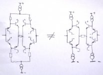
All your examples are different.
My circuit consists of a differential amplifier with a constant current source. Now the signal is not as usual, taken at the collector, but to the emitter. This is followed by the buffer. All symmetric.
All your examples are different.
This is an 'H' bridge IPS.
Since the feedback signal is buffered, you can get very fast slew rates and settling time. Usually, there is a resistor between the two diamond stages, and this ultimately sets the slew rate.
I dont think this is the so called H bridge topology as Analog devices calls it. It was also not their invention. I could be wrong here but mabe scott wurcer could inform. I have asked before but he either missed the post or didnt want to devulge. From what I gather the H bridge arrangement is quite a different circuit, I could show here if its ok with Scott and or Analog devices. Either way you might be interested in checking patents by Roy Gosser, it will get you the right answer I believe.
You have to look closely.
My circuit consists of a differential amplifier with a constant current source. Now the signal is not as usual, taken at the collector, but to the emitter. This is followed by the buffer. All symmetric.
All your examples are different.
Tell me, if you take a look at LM6172 or LT1364 how your circuit is any different. I actually did a small analysis on it as yours doesnt use the resistor. Turns out it fuctions pretty much the way the LM6172 decribes in their datasheet. This is like the Curl circuit different people will see it in their own way.
the basic idea is much older:
United States Patent 4,229,705
Takahashi , et al. October 21, 1980 Differential amplifiers
and there's no permission required to publish patented circuits - expired or not
United States Patent 4,229,705
Takahashi , et al. October 21, 1980 Differential amplifiers
and there's no permission required to publish patented circuits - expired or not
Last edited:
Ultra High Gain CMA?
Nice circuit contribution, MOSCHFET. Especially, since you figured it thru your own thought processes. Thx 😎 -🙂
A patent that is unusual for an amp running in Current-Mode operation -- an Ultra High Gain Amp; Patent number 5,614,866, Mar 25, 1997. Assigned to Elantec. It is also good reading on understanding CMA/CFA/CFB operation - see it's Background of the Invention.
View attachment US5614866.pdf
THx-RNMarsh
Last edited:
RNMarsh (5302)
My tentative conclusion from all the SIM's done recently (hundreds, perhaps) is that for SOTA designs 200-300v/usec is more in the ball park.
High slew rate is only valid for amplifiers with total negative feedback, which is equivalent to full-power bandwidth of 2 ... 5 MHz. Amplifier without negative feedback bandwidth (and hence SR) can be 10 times lower, without derating.
best regards
Petr
High slew rate is only valid for amplifiers with total negative feedback, which is equivalent to full-power bandwidth of 2 ... 5 MHz. Amplifier without negative feedback bandwidth (and hence SR) can be 10 times lower, without derating.
Huh? There is absolutely no relationship between the negative feedback and the slew rate. Negative feedback (global, local, you name it) does not affect the amplifier slew rate in any way, shape or form.
Except if you are, as many other around, confusing the "slew rate" with the "rise time", otherwise said, a large signal parameter (slew rate) with a small signal parameter (rise time). They have completely different origins in the circuit, and are also completely independent measures.
Tell me, if you take a look at LM6172 or LT1364 how your circuit is any different. I actually did a small analysis on it as yours doesnt use the resistor. Turns out it fuctions pretty much the way the LM6172 decribes in their datasheet. This is like the Curl circuit different people will see it in their own way.
In my circuit I have only 1 constant current source for the positive and the negative entrance.
I know, the invention is not high but it save components and makes layout easier.
In all my simulation the both circuits working in approximately equivalent.
(The resistant between the buffers have nothing to do with my consideration)
Attachments
Huh? There is absolutely no relationship between the negative feedback and the slew rate. Negative feedback (global, local, you name it) does not affect the amplifier slew rate in any way, shape or form.
Agreed, not directly, but in some cases the overall compensation does. If for example you use miller compensation in a GNFB amp, for a given stability, you have a given slew rate which is limited by the front end's ability to supply current. To get a faster slew rate you can trade some stability. Obviously, you could use a compensation method that doesn't load the input stage.
Lose the GNFB and you now have (a perceived) increased freedom to go faster. Global stability margins have now been removed from the equation.
And may be this is where some of the myth comes from...
Waly (5336)
Huh? There is absolutely no relationship between the negative feedback and the slew rate. Negative feedback (global, local, you name it) does not affect the amplifier slew rate in any way, shape or form.
Okay, please explain the need for the slew rate of 1000 or more times higher than the real rate of rise. Baksandal never found in real signals slew rate higher than 0.15 V/us
Best regards
Petr
Slew rate is indeed not linked to feedback ie loop gain. However, in a CFA the value of the feedback resistor plays an important role in setting the flew rate. In the H bridge structures shown previously, the feedback resistor value and the peak feedback current, which sets slew rate in a CFA, are decoupled. The slew rate, and more importantly, the settling time, for these topologies can thus be very fast.
I don't know that H bridge inputs are necessarily of bennefit in audio, since we are generally more concerned with phase margin, rather than settling time. However, still a very interesting structure worthy of exploration IMV.
I don't know that H bridge inputs are necessarily of bennefit in audio, since we are generally more concerned with phase margin, rather than settling time. However, still a very interesting structure worthy of exploration IMV.
- Home
- Amplifiers
- Solid State
- CFA Topology Audio Amplifiers