Andrew (Bonsai) is right.Ostripper that is not rail sticking you are showing there. Rail sticking is when you have overhang after the waveform exits clipping. What you have there is saturation during the clipping event that's causing phase inversion which in turn is being clamped by some mechanism. You probably still some sort of clamp or shunt to fix it ( I'd have to see the circuit to comment) but this is not rail sticking IMV.
For a real case of 'sticking' or what I call 'blocking', have a look at 2stageef-high-performance-class-ab-power-amp-200w8r-400w4r #393 & 396. Also #412, 428 434, 453, 466 and intervening posts. I think the original post which showed a sim of true 'blocking' is even earlier. Dave Zan, Harry Dymond & myself provide the pontificating while astx provides the all important 'real life' measurements.
IMHO, backed up with some listening tests, I think the amount of blocking in Toni(astx)'s amp at 20kHz is acceptable. Don't forget the amp is clipping at that point so its about whether one nasty noise sounds 'better' than another nasty noise.
The stuff that ostripper & others show isn't blocking cos the amp recovers 'instantly'.
Severe blocking (much more than astx shows) however, has a serious consequence. When the amp blocks, both OPS devices are turned on. If this happens too long, the Holy Smoke escapes and the amp dies. 😱
However, if you want to clip 100kHz sine waves into your amp, ignore everything I say and let me get some distance away before you begin 🙂
BTW, I believe clipping, overload & recovery behaviour is a far more important factor in how an amp sounds than 1 ppzillion THD.
Member
Joined 2009
Paid Member
Bjt is 1 duck from base able to carry 100 ducks from collector
Love it 🙂
BTW, I believe clipping, overload & recovery behaviour is a far more important factor in how an amp sounds than 1 ppzillion THD.
I always wondered about this and thought it must be a hangover from the tube days when amplifiers didn't have much power. A good SS amplifier usually has a fair bit of power and although it may clip, it does so rarely.
BTW, I believe clipping, overload & recovery behaviour is a far more important factor in how an amp sounds than 1 ppzillion THD.
http://www.diyaudio.com/forums/multi-way/204857-test-how-much-voltage-power-do-your-speakers-need.html lets you check exactly how often you clip.I always wondered about this and thought it must be a hangover from the tube days when amplifiers didn't have much power. A good SS amplifier usually has a fair bit of power and although it may clip, it does so rarely.
____________________
If I'm designing a commericial 50W 8R amp, I will assume the buyer will clip it often .. even on compressed pop. It's a far more important factor than 1ppzillion THD. Even the unwashed masses will notice the difference.
Last edited:
If I'm designing a commericial 50W 8R amp, I will assume the buyer will clip it often .. even on compressed pop. It's a far more important factor than 1ppzillion THD. Even the unwashed masses will notice the difference.
Exactly , no reason our DIY creations can not last for decades.
The typical 40-70W OEM "party" amp has .02-.05%THD , a power supply that
will load down before OP SOA is exceeded , VI limiting + DC protect.
With a 150+W amp , the "audiophile" will just use higher/boosted rails and-or
limit the input/gain to rarely reach clipping. Even with this scenario , who
wants that "ugly" saturated waveform ?
Bigun ..... I was clipping my 32 YO sansui HARD tonight , It became so hot
the cat slept on it. 😀
My larger amps also clip on occasion (teenagers) .. for peace of mind, I don't
want the excessive harmonics of "dirty"clipping killing my tweeters.
Tube amps have "soft" clipping , desirable distortion when overdriven (guitars)....
PS - If they (amps and tweeters) blow , where will the "ducks" go ?😀
OS
Hum, don't they use Electrolytic caps too ? 😀Exactly , no reason our DIY creations can not last for decades.
I find there are two things about electronics that helps me feel my way around:
a) voltages are always differential and all active devices operate on a differential voltage input which controls their flow of current,
b) current always flows around in loops and generates differential voltages across any resistance
c) electronics people have fancy names for circuit blocks because of historical reasons and this can constrain how you think about them, but most circuit blocks are related to each other after only a few changes in their topology
I didn't find the hydraulic analogy that useful and it took me some thinking to explain to my young son how current can flow in a capacitor...
A good hydraulic capacitor analogy is a spherical tank, with a hose connection at each 'pole'. A compliant rubber diaphragm divides the sphere into two equal halves. If water is forced into one side, the diaphragm is deformed and pushes water out of the other side. Energy is stored by the stress on the diaphragm, in a similar manner to the way that stress in the dielectric stores energy in a capacitor.
The ranch is in serious chaos when too many ducks, it blow😱 , also your tweeter is their bridge, it is vibrating when ducks are just come and go, when it is too many ducksPS - If they (amps and tweeters) blow , where will the "ducks" go ?😀
OS
 it broke down, the ducks are safe ofcourse. They doesn't coming out or the cat ate them.😀
Last edited:
Round clip need somewhat low feedback or non feedback or may be another ways, but it could be limited at the input (from pre amp stage for example).
Esperado...
what did you mean with this.
"Play with square waves on both topologies, and see what happens regarding voltages and currents in the input stages. Play with the feedback impedances too. I think you will understand why one is compressive, and the other expansive. "
I find that very very interesting would you care to elaborate a little about your findings.
michael
Input current. The faster CFA the more you need for ultra short rise/fall.
Attachments
Last edited:
It is quite complex to resume, and would be long, reason why i proposed to play with simulators. See what happens with slew-rates and closed loop bandwidth when you change feedback impedance and when you change miller comps in the VAs stage, in both topologies. Then play with caps paralleled with the feedback serial resistance. At each step, do-it at hf with large square waves (near clipping) and little ones.I find that very very interesting would you care to elaborate a little about your findings.
You will have a good knowledge of the two topologies behaviors.
Hum, don't they use Electrolytic caps too ? 😀
Most OEM's will still work at 15-20 years with original electro's (They should
still be changed) .... at 20+ years (or even 32 years) total , PS caps are
"toast".
Small signal caps (while degraded) can survive 25 years -and function.
Well designed vintage amps will survive 25+ years (semiconductors) , just the high
ripple PS caps will fail.
Panasonic , Nichicon especially ... will have 2 decades of useful life.
Derating to 105C / higher voltage is better than the typical OEM -
20+ years is almost guaranteed. Most oem's will only use 85C + 10-15%
derating (rails).
Caps in Ebay kits or "bootleg" (chinese) caps .... I've seen go in 2-4
years 😡 .
Just repaired 3 vintage amps - 2@20 YO and 1@
32 YO. 🙂
OS
I like CFA !
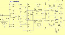
I combined a CFA with my known good EF3 - and it worked VERY well.
DC offset is still to be worked out , but I could match my VFA equivalant
plus twice the slew. 🙂
R15/14 have 50ma (big resistors) .... but that is CFB.
Easy to compensate , as well.
OS
I combined a CFA with my known good EF3 - and it worked VERY well.
DC offset is still to be worked out , but I could match my VFA equivalant
plus twice the slew. 🙂
R15/14 have 50ma (big resistors) .... but that is CFB.
Easy to compensate , as well.
OS
Attachments
http://www.diyaudio.com/forums/multi-way/204857-test-how-much-voltage-power-do-your-speakers-need.html lets you check exactly how often you clip.
____________________
If I'm designing a commericial 50W 8R amp, I will assume the buyer will clip it often .. even on compressed pop. It's a far more important factor than 1ppzillion THD. Even the unwashed masses will notice the difference.
I think it is good practice to include a clipping indicator that lights up an LED for a second when the amplifier clips for a microsecond or so. For a negative feedback amplifier, you can monitor the error signal and detect when it gets larger than normal. I've been using a 2 times 20 W in 8 ohm amplifier with such a clipping indicator since about 1994. I almost never drive it into clipping, certainly not with normal commercial recordings (including Ravel's Bolero).
I combined a CFA with my known good EF3 - and it worked VERY well.
DC offset is still to be worked out , but I could match my VFA equivalant
plus twice the slew. 🙂
R15/14 have 50ma (big resistors) .... but that is CFB.
Easy to compensate , as well.
OS
Nice!
Nice!
The input pair's matching seem to be much more critical as compared to a
VFA , adding a servo to my above circuit is easy. The issue is to either
ad a secondary PS , or just regulate a 15-0-15 V supply off of the existing
rails.
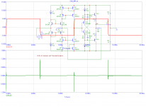
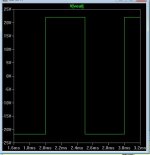
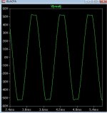
I tried the square wave with this amp ... wow ! (below-nearly 150v/us)
clipping , too...
PSRR sucks ! I will add a capacitance multiplier to both rails.
That might bring me in line with my expected VFA 😀 performance.
I can adapt 😀.
OS
Attachments
Last edited:
Glad to see you in CFA domain OS. Just one remark to your sch, would you put this out-of the feedback input buffer in front of your VFA too? Why here, because it will only degrade SQ of this otherwise nice CFA?I combined a CFA with my known good EF3 - and it worked VERY well.
I hope everyone here is striving to higher SQ, not to miss any details lost in some parts of the circuit and we do here and which happens oftenly too many times.
My suggestion would be to concentrate more to integrity of the transfered signal not so much on THD only.
Attachments
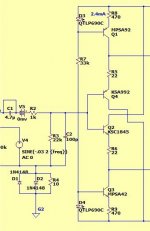
That looks like CFA - fast and no rail sticking if you keep the circuit simple with just 1 gain stage as you have done.
I use Zener regulation for the front end - works well - and fully DC couple. If you run all 4 front end transistors with the same Ic and Vce, the offsets and temp drift tend to cancel, so you end up with very good DC performance. I adjust my DC offset after the amp has warmed up, and thereafter the offset remains at 1-2mV (after warm up on subsequent switch on's) - in my view for a low loop gain gain topology, this is one of the outstanding properties of CFA.
PSRR is not as good as VFA. But, if you are going to use a servo, then you should also think about AFEC (there's a write up on my website). This provides servoing, but more importantly, you get significant improvements in PSRR - such that you end up with better performance in this regard than VFA. Simple rail filtering also goes a long way to improving things, especially once you get up above 1 kHz.
For CFA, you do need more care in the design phase and construction. But, tube amplifiers require more effort so I do not view this as a disadvantage.
Good luck and welcome to the CFA club - looking forward to your results
- Home
- Amplifiers
- Solid State
- CFA Topology Audio Amplifiers