Here, i have set the CSS collectors side, in order to have some gain.However, you are right, even without buffering devices, a current can be imposed to Q13 and to Q14 by a CCS in their emitter,
Feedback is a control process. A lot of discussion about CFA is about the way its feedback intimately works.
Well, we can look at the things the way we prefer. For the two topologies.In VFA, the control of the circuit is done by the voltage difference between the input bases and the transductance of the differential pair.
Many people think CFA work in a similar same manner, controlled by the voltage between base and emitter of the input transistors and the transconductance of the stage.
Some other people do not seem to agree.
V=RI, and transconductance is the reciprocal of a resistance. Just a superposition of a common emitter and a common base amplification in the same transistor where the resulting signal is taken at the collector.
With the risk of stating the obvious or stating something that has been stated before in this thread
Amen.
Again, i made a confusion between two of my CFA circuits... I have to take some rest !Here, i have set the CSS collectors side, in order to have some gain.
>I have no sticking issues on CFA either. Clipping in fact is very soft.
Hi Andrew,
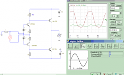
Apparently it depends on circuit details. One of Damir's earlier versions does have clipping issues, see pic, Glen K. and I had also issues.
Cheers, E.
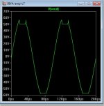
Edmond, that sticky clip is not coming from the CFA. This one clip in 2MHz and not sticking. input is 40Vpp
Add: Probably in your amp, there are some BJT with collector voltage reaching its emitter voltage (zero Vce) then ti is sticking.
Attachments
Last edited:
Hi ontoaba,
Indeed, no sticking. But that circuit has little to do with a real amp.
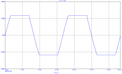
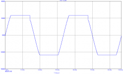
Below another example that does show sticking. It also shows how unreliable simulations can be: Only the positive halves show sticking, while the negative halves don't stick at all. The 3rd pic shows the effect (more sticking) of making R6=R7=3k that should protect the emitter followers Q3 and Q4 against overload. Clearly not a good idea.
Cheers, E.
Edmond, that sticky clip is not coming from the CFA. This one clip in 2MHz and not sticking. input is 40Vpp
Indeed, no sticking. But that circuit has little to do with a real amp.
Yes, that was indeed the case. My point is that the more current the IPS can deliver, the higher the chance of putting the next stage(s) into saturating and the harder it is to prevent it.Add: Probably in your amp, there are some BJT with collector voltage reaching its emitter voltage (zero Vce) then ti is sticking.
Below another example that does show sticking. It also shows how unreliable simulations can be: Only the positive halves show sticking, while the negative halves don't stick at all. The 3rd pic shows the effect (more sticking) of making R6=R7=3k that should protect the emitter followers Q3 and Q4 against overload. Clearly not a good idea.
Cheers, E.
Attachments

Hi ontoaba,
Indeed, no sticking. But that circuit has little to do with a real amp.
Yes, that was indeed the case. My point is that the more current the IPS can deliver, the higher the chance of putting the next stage(s) into saturating and the harder it is to prevent it.
Below another example that does show sticking. It also shows how unreliable simulations can be: Only the positive halves show sticking, while the negative halves don't stick at all. The 3rd pic shows the effect (more sticking) of making R6=R7=3k that should protect the emitter followers Q3 and Q4 against overload. Clearly not a good idea.
Cheers, E.
Hi Edmond,
It's clearly helping in my case. Maybe you push it to much into clipping, why do you want to generate a square wave from sinus?
If I push my example to much it just stops simulation, but when simulate(still very hard clipping) thare is no sticking.
BR Damir
I can see that the sticking is worse with the protection resistor set to 3k.
Why set it that high?
The worst case dissipation in the preVAS is <40mW
Does setting to 680r for a worst case dissipation of 212mW show much degradation from the zero ohm case?
What modifications would you suggest for eliminating the sticking?
Why set it that high?
The worst case dissipation in the preVAS is <40mW
Does setting to 680r for a worst case dissipation of 212mW show much degradation from the zero ohm case?
What modifications would you suggest for eliminating the sticking?
Edmond, you are using BD139/140. In my experience, these were not much better in this regard than MJE340/350 i.e terrible. You can get around it by doing some of the stuff you show above, or use a Baker clamp ( I know you don't like this latter solution, but I think its elegant). Try this same sim with a fast tranny KSA1381 and it's complement for example. The results should be better.
how unreliable simulations can be
Well, well, well, it took quite some time for you to reach to this conclusion.
ksc3503/ksa1381 (models) stick the worst. But , I feel those models most accurately
represent the real devices.
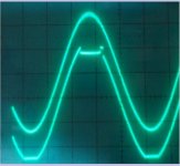
I was given a shining example by a Badger build. My simulation reflected the
real oscilloscope reading to a "tee".
Same simulation with mje340/350 , any of the BDxxx's , most of the included
LTC collection or many of my japanese models - NO sticking.
OS
represent the real devices.
I was given a shining example by a Badger build. My simulation reflected the
real oscilloscope reading to a "tee".
Same simulation with mje340/350 , any of the BDxxx's , most of the included
LTC collection or many of my japanese models - NO sticking.
OS
Attachments
@AndrewT. I wasn't my idea to use such protector resistors. It was Damir's suggestion, see this this post.
The reason I've used them in the simulation was to show that they make things even worse.
@Andrew (Bonsai), Again, it wasn't my idea to use BDxxx's and I agree with you that SA1381 and SC3503 are way better for a TIS.
>or use a Baker clamp ( I know you don't like this latter solution, but I think its elegant).
Is that so? I do use Baker (or other) clamps, even when a sim doesn't show sticking. Better safe than sorry.
Cheers, E.
Just a superposition of a common emitter and a common base amplification in the same transistor where the resulting signal is taken at the collector.
I thought the same since a long time but I do not think to have read it in any reference book. There are sometimes where saying if a transistor is in CE, CB or CC mode does not precisely describe how they really work. Considering that bipolars transistors behavior is mostly governed by their Vbe allows a very simple and more efficient to explain circuits.
Is it so that the non-ideal of the current modulation (V/I) over the feedback gnd resistor is actually expansive, where the same then the LTP backside on the VFA is compressive...?
When i was a student (Jurassic), I used to feel electricity in an hydraulic way, where voltages are pressures or water levels, current: flows, resistances: tube's diameters...I thought the same since a long time but I do not think to have read it in any reference book....Considering that bipolars transistors behavior is mostly governed by their Vbe allows a very simple and more efficient to explain circuits.
I remember to had made an hydraulic representation of a transistor at this time, with a tank and a valve, it helped-me to understand how they work.
I don't know why it is easier for lot of people to consider voltages rather than currents.
An interesting question, for me, is how other people feel electronic... or some just apply abstract formulas ?
Member
Joined 2009
Paid Member
I find there are two things about electronics that helps me feel my way around:
a) voltages are always differential and all active devices operate on a differential voltage input which controls their flow of current,
b) current always flows around in loops and generates differential voltages across any resistance
c) electronics people have fancy names for circuit blocks because of historical reasons and this can constrain how you think about them, but most circuit blocks are related to each other after only a few changes in their topology
I didn't find the hydraulic analogy that useful and it took me some thinking to explain to my young son how current can flow in a capacitor...
Last edited:
bjt's are current/flow controlled devices, Fets are voltage/pressure controlled devices, capacitors are like tanks or reservoirs storing charge (height of tank) and current (size of tank) until needed, current starts flowing when voltage(water level) drops below surface of the tank.
Ostripper that is not rail sticking you are showing there. Rail sticking is when you have overhang after the waveform exits clipping. What you have there is saturation during the clipping event that's causing phase inversion which in turn is being clamped by some mechanism. You probably still some sort of clamp or shunt to fix it ( I'd have to see the circuit to comment) but this is not rail sticking IMV.
ksc3503/ksa1381 (models) stick the worst. But , I feel those models most accurately
represent the real devices.
I was given a shining example by a Badger build. My simulation reflected the
real oscilloscope reading to a "tee".
Same simulation with mje340/350 , any of the BDxxx's , most of the included
LTC collection or many of my japanese models - NO sticking.
OS
I agree with Bonsai, no real rail sticking there.
Easy to remedy your case, use a diode in place of vas emiter resister.
Saturation - "sticking"
My point was how accurately the models simulated the actual circuit.
Unfortunately, (fortunately for the real world) I have encountered both in
my simulations - preparing me for what I was about to construct (burn up 😀).
The fairchild ksa/c 992/1845 , 1220/2690 , 1381/3503 and Cordell's ON semi
modified models are Sooooo close to reality ... nearly right to the Pf and ohm
when it comes to where the real "mcCoy" will burst forth with "magic smoke".
P vs. N channel (model wise) cannot prepare you for what you pull from the parts drawers.
For example , I would use a "wrong" device in a differential
to see how that circuit would behave with a mis-match.
I did add a "anti-saturation" diode to the real above circuit. Works well.
BTW -At gross overloads the bottom (ksc3503) would actually "stick"... as well.
I decided to generalize and call all of it "sticking" (sounds very ugly).
OS
Bjt is 1 duck from base able to carry 100 ducks from collector with it going to emitter. Higher Vbe is more base ducks ,and under voltage Vce is less ducks stock in collector, less stoc makes any base ducks carry lower ducks than usual. More ducks runs faster, but the ranch layout limit its speed.

But there also any special condition of bjt like reverse transfer and so.
But there also any special condition of bjt like reverse transfer and so.
Last edited:
- Home
- Amplifiers
- Solid State
- CFA Topology Audio Amplifiers