Disadvantage is need to use higher voltage transistors, and good ones is not easy to find.
Yes and the four transistors at the input see different operating conditions.
Understand the quest for simplicity but sometimes its a false economy. cascoding the front end is easy to layout and costs only 4 components.
Yes and the four transistors at the input see different operating conditions.
Understand the quest for simplicity but sometimes its a false economy. cascoding the front end is easy to layout and costs only 4 components.
Exactly! Some distortion canceling is lost.
Exactly! Some distortion canceling is lost.
Another advantage of the cascode front end is that you can choose the BC5x0c transistors that operate well at low Vce.
With a non cascode front end the transistor choice (high Vce) pretty much forces you to accept the consequences of quasi saturation.
you can guess where my vote would go.
Dadod,
Have you tried different OPSs? I recall in self's book a selection of different topologies with associated THDs.
Another question, is there anything to be gained by using a faster driver transistor? Eg A1930 / C5171.
Have you tried different OPSs? I recall in self's book a selection of different topologies with associated THDs.
Another question, is there anything to be gained by using a faster driver transistor? Eg A1930 / C5171.
Yes and the four transistors at the input see different operating conditions.
Understand the quest for simplicity but sometimes its a false economy. cascoding the front end is easy to layout and costs only 4 components.
But the operating conditions are symmetrical and therefore cancel.
I am talking about DC stability. At HF the conditions are of course different
At DC, running all 4 input devices with the same Vce, Ic provides very good DC stability. If however the level shifter pair operate at higher Vce (no cascode), then they will still dissipate the same power and tend to largely cancel drift.
My two CFA designs are remarkably stable DC wise and that's a function of the excellent delta Vbe canceling effect of this topology. Note all 4 input devices are physically very close to each other.
Who, from the dark side, tried the nice idea of Bryston's quad quasi complemetary for the output stage ?
Attachments
Last edited:
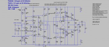
Nothing’s happening lately here. From the Dark Side another CFA amp this time with lateral MOSFET in the OPS, just to stir the pot. It uses TPC compensation but as Charry suggested a long time ago, instead to connect Miller cap to the VAS collector it’s connected to the OPS output. In this way THD20k goes down ten times. If used simple emitter follower drivers and distortion is twenty times worst.
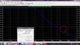
I tried that with BJT triple but it’s to unstable, here with MOSFETs is much better, but there is one caveat. Look at Loop Gain picture, there is a peak at 25 MHz about, and it’s depend of the diamond predriver transistors used. Slower transistor lower peak and vice versa, and slower transistors lower LP and consequently increase distortion significantly. I simulated with BC5xx transistors here as it gives lowest distortion, but those transistors are with to low Vce.
Any suggestion how to remove that peak?
THD20k is 1.6 ppm at 50W/8ohm.
BR Damir
Attachments
That's the reason of the comment of L.C. about diamonds. Tried to set a little cap in // with the feedback resistance ?there is a peak at 25 MHz about, and it’s depend of the diamond predriver transistors used. Slower transistor lower peak and vice versa, and slower transistors lower LP and consequently increase distortion significantly.
Any suggestion how to remove that peak?
Your best result till now. I never try BJT for ops anymore.
Last edited:
That's the reason of the comment of L.C. about diamonds. Tried to set a little cap in // with the feedback resistance ?
Your best result till now. I never try BJT for ops anymore.
That cap increases phase margin, and just aggravates the peak.
I see Wahab and forr are conspicuous by there absence. 😀
Do I miss you ?
I asked you some questions and had no response.
I would not like to bother you by repeating them.
I very much dislike proofs of low distortion only based on simulations (their numbers now become excessive every and they bore me) or repetitive claims of better sound which won't resist one minute in blind tests. So recently, I did no see anything I had to comment.
I would not have made the following if you have not written your remark.
It is quite depressing that a french member refuses to read Douglas Self's book for the reasons he has given. Douglas is extremely easy to read and provides an amount of verified facts on amplification for which there is absolutely no equivalent. People having former certitudes have lost them when reading it.
I know Douglas's Electronics World articles on amplification since the first published in 1993 (at that time, I even knew his previous "Mosfet design"). It was not only before 2005 that he began to become really known and to have influence in France. I could have been very proud to know his works much before almost everybody in my country but in fact, I was very sad about the lack of curiosity of my french contemporaries.
Happily, this time is over. But not completely, as we see.
Increasing the feedback impedance will decrease the peak, but increase HD, i fear.
No, this peak is comming from Miller cap encompassing OPS, nothing to do with the feedback impedance.
You mean the peak is the same with OPS all alone ?No, this peak is comming from Miller cap encompassing OPS, nothing to do with the feedback impedance.
Increasing the feedback impedance will reduce the overall bandwidth, so, can compensate more or less this resonance at the HF limit ?
Last edited:
"I very much dislike proofs of low distortion only based on simulations (their numbers now become excessive every and they bore me) or repetitive claims of better sound which won't resist one minute in blind tests. So recently, I did no see anything I had to comment."
I am surprised at this forr since you were the one a few pages back telling us that CFA was no good and how you can get VFA THD down to -130 dB.
I am surprised at this forr since you were the one a few pages back telling us that CFA was no good and how you can get VFA THD down to -130 dB.
Esperado noticed that Q9 was wrong polarity. Now with correct one the peak has gone but THD20k increased to 3 ppm. Strange how LTspice does some tricks, some water on the mill ones who don't like simulation.
Thanks Esperado
Thanks Esperado
"I very much dislike proofs of low distortion only based on simulations (their numbers now become excessive every and they bore me) or repetitive claims of better sound which won't resist one minute in blind tests. So recently, I did no see anything I had to comment."
I am surprised at this forr since you were the one a few pages back telling us that CFA was no good and how you can get VFA THD down to -130 dB.
Did I ? All depends on what you, me, or third parties, mean by "good".
This is the oldest semantic problem since the human language exists.
After all trials I am back to the schematic manso showed here http://www.diyaudio.com/forums/solid-state/240712-cfa-topology-audio-amplifiers-47.html#post3605474
Manso persist that the best compensation for CFA is shunt type, and I used Miller compensation, actually TPC. Could be that this is wrong approach and I would like to hear from manso with explanation.
BR Damir
Manso persist that the best compensation for CFA is shunt type, and I used Miller compensation, actually TPC. Could be that this is wrong approach and I would like to hear from manso with explanation.
BR Damir
I noticed too that we have come pretty much full circle. My trials have suggested that a combination approach seems to work best some lead lag + some form of miller. Either of the two pole miller approaches (TMC, TPC) seem the best for THD performance. Plain miller always seems to dissappoint.
Plain shunt I could never get to work very well in sims.
At least DTMC + lead lag works in reality and appears very stable even without an output inductor filter.
Plain shunt I could never get to work very well in sims.
At least DTMC + lead lag works in reality and appears very stable even without an output inductor filter.
- Home
- Amplifiers
- Solid State
- CFA Topology Audio Amplifiers