How about a definition of 'better overall amp'?I still feel that introducing a 'standard' output stage at this point may hide some opportunities for better amps.
I have suggested to test the ips and vas/tis independently of an ops config to establish is a cfa is/is not 'better' than the vaf config.
True, in the end, you still need an ops.
But if the cfa in isolation has true advantages, which are subsequently swamped by the ops, the task is clear: find a different ops (or a different vas/tis-to-ops interface) that does not swamp the cfa advantage.
That may be another extensive project in itself, but it does hold the promise of better overall amps. Assuming of course the cfa is better; if not, no harm is done anyway.
My definition is Equal or better performance with less complexity. It's pretty obvious that my #499 circuit does this by practically ALL objective measures compared to MUCH more complex amps.
One of my naive views is that the simpler the circuit, the closer 'real life' will be to SPICE world which is why I take with a large pinch of salt the performance of SPICE circuits with zillion active devices.
___________________
'Testing' the IPS & VAS separately from the OPS leads inevitably to my #1007 circuit. It's no more stupid or sensible than the other proposals with 'ideal' OPS. In fact, its performance exceeds the other proposals by a large margin.
Guru Brad, you're not allowed to comment. Let the unwashed masses work it out for themselves. 😀
That's not to say I spurn testing individual stages separately but this is usually to find if certain characeteristics are relevant. I do this very carefully in #1215
Another example of why looking at stages separate is often non-productive. Using Current Conveyors (mirrors with precise gain & low THD) to replace the crude enhanced VAS in Bonsai's qx-Amp will produce NO overall improvement. This is cos the major THD mechanisms are to do with the interaction of VAS with both IPS & OPS.
An example of the advantage of a Holistic view is that 'pure Cherry' improves the interaction with both IPS & OPS. One could consider a 'pure Cherry' VAS/OPS as a single stage with nearly ideal properties. In fact it does all this while da whole shebang is simpler than da supa low THD (??) OPS alone 😱
Richard,
Indeed you can leave AFEC out and the distortion is about 7 ppm at full power - and no need add complexity to go below this IMV. But, AFEC gives you offset servoing and pushes PSRR to levels much better than VFA's - think of it as simpler, cheaper and more effective cap mulitplier.
I am not going to go with you on the 'simple' CFA front end Richard. It's neat, but I am not a fan of the caps and as I mentioned earlier, I don't believe it scales easily.
I'm only saying we shouldn't dismiss 'simple', especially for less complex amps with designed THD more than 10ppm. I'm certain that when we get below 1ppm, Diamond will show big advantage.I am not going to go with you on the 'simple' CFA front end Richard. It's neat, but I am not a fan of the caps and as I mentioned earlier, I don't believe it scales easily.
Theoretically, with perfect matching bla bla (loadsa caveats re operating conditions), Diamond has 10x less THD than 'simple'. But the matching requirements for 'simple' are MUCH less stringent. In practice, with most CFAs, the 3dB or so extra LG with simple is the important feature.
I'm still open about this. My offset stuff is just from reading your stuff and LC's VSSA thread. I've no 'real life' experience for this important issue.
When Marshy gives us a price for the Taipan oil filled caps in Unobtainium cases, I might do an about turn 😱
I'm also re-reading AFEC and doodling to see if the AFEC injection point can be used to get rid of the evil caps in 'simple'. 🙂Indeed you can leave AFEC out and the distortion is about 7 ppm at full power - and no need add complexity to go below this IMV. But, AFEC gives you offset servoing and pushes PSRR to levels much better than VFA's - think of it as simpler, cheaper and more effective cap mulitplier.
qx-Amp is well within striking distance of the best VFA amps for measured stuff.
Don't think scalabiltiy of 'simple' is a problem. Changing the 300W 8R qx-Amp to 'simple' was very straightforward.
There also seems to be some subtle advantages going from the less complex nx-Amp to qx-Amp which I'm trying to understand. Compensation is easier for a start.
Unlike some proposals here, the extra complexity with qx-Amp is accompanied by very worthwhile gains. And it scales 'down' too. A very stripped down version of 'simple' qx-Amp beats Dadod's circuit on all counts and uses half the active devices.
Damir, I'm only pointing out that you have in the past done some very simple circuits yourself with better performance than your #1253.
_____________
So to sum up, I'm giving my vote to Bonsai's qx-Amp but not ruling out evil 'simple' mods to it. 😀
1- Bonsai, you did not answered this question i asked before: did-you use what you call AFEC *in real world*, and, if yes, and as it is easy to plug-it in and out, what are the differences from a listening point of view ?1- Indeed you can leave AFEC out and the distortion is about 7 ppm at full power - and no need add complexity to go below this IMV. But, AFEC gives you offset servoing and pushes PSRR to levels much better than VFA's - think of it as simpler, cheaper and more effective cap mulitplier.
2- I am not going to go with you on the 'simple' CFA front end Richard. It's neat, but I am not a fan of the caps and as I mentioned earlier, I don't believe it scales easily.
2- Who oblige-you to use caps for a simple CFA input stage ?
Richard - ok I think we are broadly aligned exdecept on the 'simple' aspect - if you prefer SCFA over DCFA that then becomes the designers perogative.
I dont want to push qx-Amp on this thread - there are other valid designs and I dont think we can close off the discussion yet.
I dont want to push qx-Amp on this thread - there are other valid designs and I dont think we can close off the discussion yet.
Esperado
no not tried in a practical amp yet. I will start layout on the qx-Amp in the next month or so. This will incorporate AFEC. I am also thinking about an upgraded nx-Amp with cascoded front end, 3 output pairs and 60V rails and AFEC . . . but my mian reason for the AFEC bit on both these designs is for the PSRR and DC servoing (I can drop 1 potentiometer).
no not tried in a practical amp yet. I will start layout on the qx-Amp in the next month or so. This will incorporate AFEC. I am also thinking about an upgraded nx-Amp with cascoded front end, 3 output pairs and 60V rails and AFEC . . . but my mian reason for the AFEC bit on both these designs is for the PSRR and DC servoing (I can drop 1 potentiometer).
Last edited:
KGRLee:
Forget the caps... Marshy want group buy of dancing virgins sent to his home to liven up the party going on over here. [ I wish]
-RNMarshy
Forget the caps... Marshy want group buy of dancing virgins sent to his home to liven up the party going on over here. [ I wish]
-RNMarshy
The Unity Loop Gain Frequency is where the system runs out of Feedback. The EXACT gain and phase behaviour near this frequency determines if the system is stable, if it peaks, rings etc.Regarding ULGF why is 3MHz seen as aggressive? What are the mechanisms that come into play at >3MHz that cause the problems?
The response of a system is determined by 'poles'. Above the pole frequency, the response drops off at 6dB/octave and the phase tends towards 90 degrees. Each active device will have at least one pole. Each capacitor which affects the HF response will also introduce a pole (they can also introduce 'zeros' which are the opposite of poles but I won't go into that.
When you compensate an amplifier for stability, you attempt to shape its frequency response with passive capacitors so its repeatable. For this, the poles introduced by the active devices should be at as high a frequency as possible so they don't affect what's happening at the ULGF. The compensation is often specified by the ULGF.
A high ULGF is living dangerously cos you are getting close to the evil, unknown poles over which you have little control. But in most compensation schemes, a high ULGF also gives more feedback at audio frequencies so there is a delicate trade-off. Self & Cordell explain this trade-off between more feedback, high ULGF with less distortions but also less stability ... and less feedback, low ULGF with more distortion but more stable.
This most easily and accurately done with a Tian probe.regarding open loop gain is this best simulated by changing the feedback shunt resistor to something very small and performing an AC Analysis or by breaking the loop like when doing PM/GM sims?
An excellent one is in your LTspice directory as
examples\educational\LoopGain2.asc
Making the feedback shunt resistor small or breaking the loop can give good results in some simple cases but can be widely wrong in others. The Tian probe is simpler to use and always accurate.
Learn to use one.
Kgrlee,
Thank you for your explanation. It would appear that it is these unknown poles that are the problem. Or at least ones that LTSpice doesn't model. I spent many hours looking at my "creation" wondering why it was oscillating. It was by chance Bonsai mentioned about what he thought is too high a ULGF. I tried reducing the ULGF and the oscillation stopped. I never really understood why as the sims showed nothing obviously wrong. Need to work out where these unknown poles come from.
I understand the idea of at least one type of zero. In that you can use capacitors and resistors to cancel some poles. It's an area I need to understand better. eg Nyquist theory.
The tian probe... It looks like some random code to me at present. It appears to be a necessary evil to get an understanding of this.
From what you saying is that its all about the loop gain plot. This would be consistent with typical THD profiles. Reducing the feedback resistor produced a plot that looked wildly unrealistic with flat gain into the MHz.
Now know what needs to be studied, thank you 🙂
Apologies to all for de-railing the thread a little.
Did somebody had got convincing improvement with triples, using Laterals (~infinite current gain & high non linear parasitic capacitances) ?maybe find out in sim if this or one of similar variation would be better if adapted here.
I believe the only way to improve out stage numbers is local feedback (or any kind of local error correction) to get rid of both the distortions of the power devices and class B crossover's ones.
The problem is it is hard to get-it effective, stable (Yet alone, imagine in a closed-loop system.), and simple without killing bandwidth, adding a crowd in the signal path, or any horrible sensitive pot to tune rejection.
Apart numbers, what is the benefit ? With 150mA of quiescent, preferred for laterals, a powerfull enough amp, and high efficiency speakers, all the sustained musical signals (where you can feel the distortion) will be class A, and a ( little ) crossover distortion will just give more presence to the high level transients.
After all, we usually feel very simple current feedback amps to be 'fluid', transparent and producing no listening fatigue.
Am-i wrong, Mr Pass or Mr. Hirraga ?
Each time i had tried in my studios one of those very complicated and expensive amplifiers with a lot of tranies, i was not convinced at all by the way they sounded. Kind of confusion, hard to separate instruments.
With all those servos, assistances and regulators in our modern cars, we lose the simple and fabulous pleasure of a karting and its direct contact with the road.
All wires and printed boards tracks are inductances, and build parasitic capacitances with the next tracks ... Sometimes it can help, not often ;-)Or at least ones that LTSpice doesn't model
And models are caricatures.
Last edited:
Should also point out that the response of a pole doesn't really show itself until you get past the pole frequency (at which it is -3dB).A high ULGF is living dangerously cos you are getting close to the evil, unknown poles over which you have little control.
But the Phase introduced by the pole is significant a decade below the pole frequency .. which is why you need to steer well clear.
Another concept da pedants will try to obfuscate is Pole Splitting.
Certain types of compensation, eg plain Miller 'move' the pole introduced by an active device to a higher frequency. They'll argue over when or if this is happening .. but the practical effect is that the Miller capacitor sets the dominant pole and you can usually ignore everything else including what happens to the 'device pole'.
I beg forgiveness from da pedants for my naive and irreverent exposition of their beloved poles & zeros. 🙂
________________
Christophe, you are right!Esperado said:Apart numbers, what is the benefit ? With 150mA of quiescent, preferred for laterals, a powerfull enough amp, and high efficiency speakers, all the sustained musical signals (where you can feel the distortion) will be class A, and a ( little ) crossover distortion will just give more presence to the high level transients.
After all, we usually feel very simple current feedback amps to be 'fluid', transparent and producing no listening fatigue.
This evil thread has somehow got us chasing numbers. 😱 Even Bonsai, who has some very nice simple CFAs is now planning to make complex versions. Damir, has gone completely over to the Dark Side and proposed the most complex CFA I've seen.
I must resist this trend myself.
Alas, we have no more stock of Taipan-oil capacitors from Mr. Marsh cos no more Virgins .. so may have to abandon VSSA type simplicity . 🙂
Last edited:
Dadod,
Please could you post the .asc file for your simplified CFA. I'd like to try a couple of ideas out on it. They probably won't improve things but may answer some questions I have in my mind.
Thank you
Paul
It's here.
Attachments
"Even Bonsai, who has some very nice simple CFAs is now planning to make complex versions"
No no no. I am simply refining it a bit!
😀
No no no. I am simply refining it a bit!
😀
Damir, has gone completely over to the Dark Side and proposed the most complex CFA I've seen.
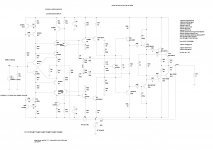
One more from the Dark Side 😀.
This uses TPC and THD20k is down from 7.3ppm to 4.9 ppm, only 3.5dB down but everything counts on the Dark Side.
BR Damir
Attachments
That's looking good damir. It's a lot simpler than your earlier designs and you are at <5 ppm.
You could drop the current sources and go for Zener regulation for the FE for further simplicy. I found zeners work extremely well, and they are actually not bad noise wise if you go above about 8 volts.
You could drop the current sources and go for Zener regulation for the FE for further simplicy. I found zeners work extremely well, and they are actually not bad noise wise if you go above about 8 volts.
That's looking good damir. It's a lot simpler than your earlier designs and you are at <5 ppm.
You could drop the current sources and go for Zener regulation for the FE for further simplicy. I found zeners work extremely well, and they are actually not bad noise wise if you go above about 8 volts.
Thanks Bonsai,
I simulated with 12V zeners and got a bit higher distortion(increase from 5 to 6 ppm) and to get similar result as with CCS it needs to bootstrap the zeners(probably it needs parallel caps to zeners too) and it is not any more simpler. I kept the same condition on the cascode transistors of carse. I prefare CCS as small transistors are very cheap and DC compensation is simple by changing one side CCS currenz a bit.
Try your CFA with CCs and you could be pleasantly surprised with result.
BR Damir
Amateur Offering...
Esperado - The track to track capacitances were about the only parasistic that wasn't modelled (or at least attempted to model)
Kgrlee - It sort of makes sense if you assume the output stage to have a pole at about 40Mhz. One decade down is 4Mhz. Probably best to have a ULGF below 4Mhz in this case.
Tonight's entertainment...
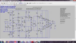
Been playing about a little with Dadod's simple CFA and ended up deviating quite a bit. This is the result... Taken what I thought were the key parts of my monstrosity and put them into this.
Costs a few components and 4 transistors extra.
THD20 @ 50W / 8R = 0.000138%
THD1 @ 50W / 8R = 0.000001%
I think the PM / GM are ok. Slew rate is about 77V/uS, so not good.
(Prepared for complaints about complexity)
PS Dadod, your designs are always so well optimised. 🙂
Esperado - The track to track capacitances were about the only parasistic that wasn't modelled (or at least attempted to model)
Kgrlee - It sort of makes sense if you assume the output stage to have a pole at about 40Mhz. One decade down is 4Mhz. Probably best to have a ULGF below 4Mhz in this case.
Tonight's entertainment...
Been playing about a little with Dadod's simple CFA and ended up deviating quite a bit. This is the result... Taken what I thought were the key parts of my monstrosity and put them into this.
Costs a few components and 4 transistors extra.
THD20 @ 50W / 8R = 0.000138%
THD1 @ 50W / 8R = 0.000001%
I think the PM / GM are ok. Slew rate is about 77V/uS, so not good.
(Prepared for complaints about complexity)
PS Dadod, your designs are always so well optimised. 🙂
Attachments
Esperado - The track to track capacitances were about the only parasistic that wasn't modelled (or at least attempted to model)
Kgrlee - It sort of makes sense if you assume the output stage to have a pole at about 40Mhz. One decade down is 4Mhz. Probably best to have a ULGF below 4Mhz in this case.
Tonight's entertainment...
Been playing about a little with Dadod's simple CFA and ended up deviating quite a bit. This is the result... Taken what I thought were the key parts of my monstrosity and put them into this.
Costs a few components and 4 transistors extra.
THD20 @ 50W / 8R = 0.000138%
THD1 @ 50W / 8R = 0.000001%
I think the PM / GM are ok. Slew rate is about 77V/uS, so not good.
(Prepared for complaints about complexity)
PS Dadod, your designs are always so well optimised. 🙂
Welcome to the Dark Side. Could you now post .asc file.
BR Damir
P.S. I suppose you increased LG?
Last edited:
Welcome to the Dark Side. Could you now post .asc file.
BR Damir
P.S. I suppose you increased LG?
"With our combined strength, we can end this destructive conflict, and bring order to the galaxy." - Darth Vader 😀
Here is the .asc file. Would be good to get an experienced opinion. I think LG has increased. I'm still trying to figure out the tian probe properly.
Warning: Only had about 7 months experience in amp design so may have made mistakes.
Paul
Attachments
Welcome to the Dark Side. Could you now post .asc file.
BR Damir
P.S. I suppose you increased LG?
You increased LG to 130dB at 100Hz and 60dB at 20kHz, in my simulation it is not stable. I think your TMC is not optimized.
- Home
- Amplifiers
- Solid State
- CFA Topology Audio Amplifiers