Beginner question - what is telling you its not stable?
Plot of the Loop Gain. Now is late could we proceed with it tomorrow?
Plot of the Loop Gain. Now is late could we proceed with it tomorrow?
With pleasure. I appreciate you offering to help educate me. 🙂
With pleasure. I appreciate you offering to help educate me. 🙂
Hi mcd99uk,
I am not the one to educate, but to be educated, lot of things to learn about audio electronic.
I made a small mistake in the first simulation of your modification, I did not notice that you changed RCs at the gain stage output(R22 C3 , R23 C4).
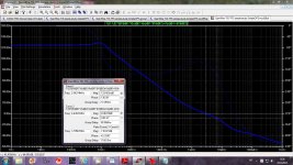
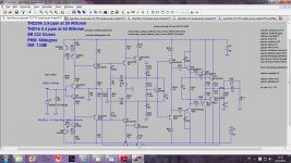
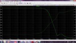
Here is a new loop gain simulation. I use Tian probe as in LTspice Loop Gain 2 example. As this is current feedback amp simple voltage probe is not good enough(as for VFA sim), it needs both voltage and current probe.
This sim looks better, no oscillation but still to low PHM(phase margin) and GM(gain margin). The TMC caps normally are not equal if to get better PHM, GM and lower distortion in the same time.
Here is my simulation, PHM is 29degree(180 minus 151) and GM is 4.66 dB.
I like how you increased LG, active load to increase the gain and enhanced VAS(TIS), very nice. I was trying on the similar way(with current mirrors) but did not succeeded yet.
I will try to optimize it(maybe better to use TPC) today to see if this distortion decrease is worth added complexity, not that small transistors are expensive.
BR Damir
Attachments

My hands are faster then my eyes. I started to simulate before you sent .asc file and in last simulation I forgot to change the feedback resistors values.
Here is new sim, better but still not so good, Higher feedback resistor values probably lower slew rate.
BR Damir
Here is new sim, better but still not so good, Higher feedback resistor values probably lower slew rate.
BR Damir
Attachments
Oh yes they are. On an industrial point of view.not that small transistors are expensive.
They need to be mounted, they often come with added resistances, increase of surface of the printed board, holes to dig if not SMD. More than this, they increase the risk of defect, and, because their own tolerances, the risk to get the all board out of tolerance. Even a strap is very expensive.
More important, and this time from an audiophile point of view, each added device in the signal path brings 'blur', reduce bandwidth and slew rate, add poles.
Looking at your file, Dadod, my first feeling was not how to improve distortion, i cannot even see them in my microscope or distortiometer, but how to improve slew-rate and reduce the component's number.
I'm sure of one point: double your distortion values, triple your slew rate, and you'll have a better amplifier.
One point is impressive, dadod, you have made the demonstration that one (not everybody ;-) can make a CFA with less distortion than most of VFAs.
This said, sims are an utopic world. And i wonder how could measure your amp with average components not matched, out of the box (industrial), in real world, comparing with a much simpler one in the same conditions. Not to talk of stability problems witch are increased with the number of components on board.
About Tian probe,
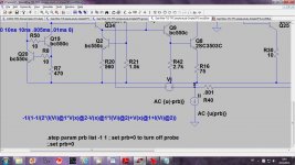
You can see on this picture that I have the text in the schematic.
-1/(1-1/(2*(I(Vi)@1*V(x)@2-V(x)@1*I(Vi)@2)+V(x)@1+I(Vi)@2))
and spice directive
.step param prb list -1 1 ; set prb=0 to turn off probe
;.set prb=0
When you run .ac, plot, let say vout then change it to
-1/(1-1/(2*(I(Vi)@1*V(x)@2-V(x)@1*I(Vi)@2)+V(x)@1+I(Vi)@2))
When you want to sim .tran then change spice directive to
;.step param prb list -1 1 ; set prb=0 to turn off probe
.set prb=0
BR Damir
Attachments
Oh yes they are. On an industrial point of view.
They need to be mounted, they often come with added resistances, increase of surface of the printed board, holes to dig if not SMD. More than this, they increase the risk of defect, and, because their own tolerances, the risk to get the all board out of tolerance. Even a strap is very expensive.
More important, and this time from an audiophile point of view, each added device in the signal path brings 'blur', reduce bandwidth and slew rate, add poles.
Looking at your file, Dadod, my first feeling was not how to improve distortion, i cannot even see them in my microscope or distortiometer, but how to improve slew-rate and reduce the component's number.
I'm sure of one point: double your distortion values, triple your slew rate, and you'll have a better amplifier.
One point is impressive, dadod, you have made the demonstration that one (not everybody ;-) can make a CFA with less distortion than most of VFAs.
This said, sims are an utopic world. And i wonder how could measure your amp with average components not matched, out of the box (industrial), in real world, comparing with a much simpler one in the same conditions. Not to talk of stability problems witch are increased with the number of components on board.
Christophe, you can come over to the Dark Side too - I love it - and read D. Self books.
BR Damir
I'm afraid of the ghosts 🙂Christophe, you can come over to the Dark Side too - I love it - and read D. Self books.
About mister Self, i'm crossed against him since at my question:
- "Can-you write a book about audio engineering without a word on current feedback topology ?",
He answered an arrogant and not so clever:
- "Oh yes, i can.".
And i'm too stupid to understand all the complicated things he writes, sometimes, while i understand and generally agree each word and the spaces between them of what I've read from Bob C. (not to oppose them)
With age, we tend to simplify our way to think (and feel) and prefer to look at schematics than words to describe them.
BTW, about LTSpice and Tian probe, what the hell are doing their devs ? Why this is not set by the user interface ? We are in 2013, and open loop bandwidth an indispensable tool.
Based on your experience, is the AC plot at the VAS input not accurate enough to have a look at the open loop bandwidth ?
Hi mcd99uk,
I am not the one to educate, but to be educated, lot of things to learn about audio electronic.
I made a small mistake in the first simulation of your modification, I did not notice that you changed RCs at the gain stage output(R22 C3 , R23 C4).
Here is a new loop gain simulation. I use Tian probe as in LTspice Loop Gain 2 example. As this is current feedback amp simple voltage probe is not good enough(as for VFA sim), it needs both voltage and current probe.
This sim looks better, no oscillation but still to low PHM(phase margin) and GM(gain margin). The TMC caps normally are not equal if to get better PHM, GM and lower distortion in the same time.
Here is my simulation, PHM is 29degree(180 minus 151) and GM is 4.66 dB.
I like how you increased LG, active load to increase the gain and enhanced VAS(TIS), very nice. I was trying on the similar way(with current mirrors) but did not succeeded yet.
I will try to optimize it(maybe better to use TPC) today to see if this distortion decrease is worth added complexity, not that small transistors are expensive.
BR Damir
Thank you for looking at the circuit. Evidently, I'm not using the tian probe properly yet. Will have another try later. Going to follow your instructions to the letter.
The Enhanced VAS configuration wasn't my creation. It was lifted from Edmond's MCP amplifiers. Although in this the VAS was cascoded as well. It seemed a very elegant solution and I just wanted to highlight it in this thread before the enhanced VAS was rejected. The only thing I have noticed is that this configuration seems to require some loading on the output to counter some closed loop peaking.
TPC may work better than TMC and better values may improve things.
The problem I found with reducing the feedback resistors was a peaking in the closed loop response. Haven't found a good way of controlling this yet.
Paul
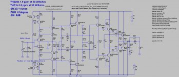
I don't know why I insisted to use Baxandall pairs as VAS(TIS).
Now I changed it to the simple enhanced VAS and results are much better.
Sorry mcd99uk, but it looks that all increase in complexity is not needed.
BR Damir
ps probably because it worked so well in the non GNFB GainWire preamp.
Now I changed it to the simple enhanced VAS and results are much better.
Sorry mcd99uk, but it looks that all increase in complexity is not needed.
BR Damir
ps probably because it worked so well in the non GNFB GainWire preamp.
Attachments
Last edited:
I'm afraid of the ghosts 🙂
About mister Self, i'm crossed against him since at my question:
- "Can-you write a book about audio engineering without a word on current feedback topology ?",
He answered an arrogant and not so clever:
- "Oh yes, i can.".
And i'm too stupid to understand all the complicated things he writes, sometimes, while i understand and generally agree each word and the spaces between them of what I've read from Bob C. (not to oppose them)
With age, we tend to simplify our way to think (and feel) and prefer to look at schematics than words to describe them.
BTW, about LTSpice and Tian probe, what the hell are doing their devs ? Why this is not set by the user interface ? We are in 2013, and open loop bandwidth an indispensable tool.
Based on your experience, is the AC plot at the VAS input not accurate enough to have a look at the open loop bandwidth ?
Christophe, you know we are of the same age, but I am trying to be jung in my hart and learn new things, you know, to delay alzheimer.
Regarding open loop gain, how you simulate it? Definitely it's not accurate enough to do it at VAS input or VAS output, OPS is the main constrain.
BR Damir
I don't know why I insisted to use Baxandall pairs as VAS(TIS).
Now I changed it to the simple enhanced VAS and results are much better.
Sorry mcd99uk, but it looks that all increase in complexity is not needed.
BR Damir
ps probably because it worked so well in the non GNFB GainWire preamp.
No need for the sorry.
Baxandalls are apparently good at rejecting current distortion from the OPS though. Wonder if in real life this would prove an advantage.
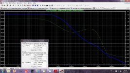
The only real difference between our circuits is that the extra complexity helps with defining the VAS current. The question is whether this VAS fighting issue worth the extra complexity?
The only real difference between our circuits is that the extra complexity helps with defining the VAS current. The question is whether this VAS fighting issue worth the extra complexity?
And increase of the loop gain at 1kHz and vanishing low distortion at that and lower frequency
Very nice damir 🙂
Its clear you are into very high perfmance teritory now - low distortion, high SR and wide loop bandwidth.
I would now go through a simplification process to see what active devices you can leave off.
Front end current source > Zener Reg
Cascode for level shifter > you can try to leave these out (might be a problem though)
Very nice damir 🙂
Its clear you are into very high perfmance teritory now - low distortion, high SR and wide loop bandwidth.
I would now go through a simplification process to see what active devices you can leave off.
Front end current source > Zener Reg
Cascode for level shifter > you can try to leave these out (might be a problem though)
Simpler, but I will not go for zener as I explained why not before.
Attachments
What's your PSRR? This one area you have to watch with CFA.
I see your rails are sized for about 100 W - what's it like at full power. You should be able to get well under 10 ppm.
I see your rails are sized for about 100 W - what's it like at full power. You should be able to get well under 10 ppm.
Last edited:
What's your PSRR? This one area you have to watch with CFA.
I see your rails are sized for about 100 W - what's it like at full power. You should be able to get well under 10 ppm.
110 W THD20k 4.28ppm
PSSR 53.3dB
Attachments
Ah - I see you have no front end cascodes - that's great.
Disadvantage is need to use higher voltage transistors, and good ones is not easy to find.
- Home
- Amplifiers
- Solid State
- CFA Topology Audio Amplifiers