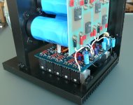
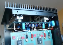
I've experimenting with a sort of 3D-power amp module, with the aim to a) put everything in the output stage on the heatsink, and b) make all connections including to the power supply very short but still away from sensitive circuit parts.
One implementation shown in the pictures - you can see that the (pre) drivers are on the inside of the aluminum bars. The power supply connections are short and orthogonal to the board.
As Bob noted, putting (pre)drivers on the main heat sinks can be too much for thermal stability, so I now would do it different, placing the (pre)drivers on the PCB with their own small heatsink.
However such a module approach is very good electrically, with very little crosstalk and almost no supply induced distortion. Also for servicing you can just replace a complete module very easily and quickly.
Jan
Attachments
I did it a bit differently, pre-drivers are small and dissipate little and no heathsink, drivers and be multiplier transistor are on separate small heathsink, and only output transistors are on the main heathsink and off course TT diodes assisting Vbe multiplier.
For thermal comp, I use a two transistor CFP. The sense transistor is a SOT23 device, thermally coupled to one of the OPS collected leads, and both driver and pre drivers are on the same heatsink. I then use a NTC to provide a second compensation point.
I've experimenting with a sort of 3D-power amp module, with the aim to a) put everything in the output stage on the heatsink, and b) make all connections including to the power supply very short but still away from sensitive circuit parts.
One implementation shown in the pictures - you can see that the (pre) drivers are on the inside of the aluminum bars. The power supply connections are short and orthogonal to the board.
As Bob noted, putting (pre)drivers on the main heat sinks can be too much for thermal stability, so I now would do it different, placing the (pre)drivers on the PCB with their own small heatsink.
However such a module approach is very good electrically, with very little crosstalk and almost no supply induced distortion. Also for servicing you can just replace a complete module very easily and quickly.
Jan
Nice looking build Jan!
🙂
Hello Dadod,
I like your amplifier build, but I would like to say that it is good to use fusible or non flammable resistors on the output stage as it prevents board damage with an output stage failure . They look like carbon on the bases on the output devices I would use fusible types , I m not sure what RE (0.22R ) types you are using but I would use metal oxide types there if you are not already.
Thank you PHEONIX,
I don't have any kind of protection on that board as I use a power regulator with all protection needed, look here, schematics in pdf http://www.diyaudio.com/forums/solid-state/182554-thermaltrak-tmc-amp-10.html#post3031504. After prolong use of that amp I follow that route for all my new amps.
I use Re of 0.16R made from parallel metal oxide types resistors. That board was not fully assembled yet, some components are missing as some Re.
I've experimenting with a sort of 3D-power amp module, with the aim to a) put everything in the output stage on the heatsink, and b) make all connections including to the power supply very short but still away from sensitive circuit parts.
One implementation shown in the pictures - you can see that the (pre) drivers are on the inside of the aluminum bars. The power supply connections are short and orthogonal to the board.
As Bob noted, putting (pre)drivers on the main heat sinks can be too much for thermal stability, so I now would do it different, placing the (pre)drivers on the PCB with their own small heatsink.
However such a module approach is very good electrically, with very little crosstalk and almost no supply induced distortion. Also for servicing you can just replace a complete module very easily and quickly.
Jan
Very nice and clean built, only problem I see here is servicing.
I did it a bit differently, pre-drivers are small and dissipate little and no heathsink, drivers and be multiplier transistor are on separate small heathsink, and only output transistors are on the main heathsink and off course TT diodes assisting Vbe multiplier.
Damir, very good build, but Thermaltrack is a bit different story - it gives you more sensors, and I like the idea of putting 2 of them are between the emitters of the driver stage, as I saw in your schematic.
No, sharing the schematics would be a futile exercise. It's way to complicated for this place that considers the number of transistors in the gain stages as the supreme design/performance/sound quality criteria, 6 devices being the supreme ear Nirvana. The gain stages have no less than 56 SMD transistors, out of which 34 are dual devices (pnp/pnp, npn/npn, pnp/npn).
The instrument is a Rohde&Schwartz UPD in our lab. It's the AP27xx head-to- head competitor, a little less performant (higher noise floor), but much more friendly (computer and LCD display are included), and has all the options that AP adds only for big money.
Here's a photo of the gain stages board. The opamp in the center is the servo.
Hello Wally,
Looking at you image of your PCB loaded with smd parts what fusible parts do you use if any, how about the RE types in your final construction are they metal oxide types or are they wire wound types.
I've experimenting with a sort of 3D-power amp module, with the aim to a) put everything in the output stage on the heatsink, and b) make all connections including to the power supply very short but still away from sensitive circuit parts.
One implementation shown in the pictures - you can see that the (pre) drivers are on the inside of the aluminum bars. The power supply connections are short and orthogonal to the board.
As Bob noted, putting (pre)drivers on the main heat sinks can be too much for thermal stability, so I now would do it different, placing the (pre)drivers on the PCB with their own small heatsink.
However such a module approach is very good electrically, with very little crosstalk and almost no supply induced distortion. Also for servicing you can just replace a complete module very easily and quickly.
Jan
3D approach is great! Something I'd like to experiment with...
My experience with placing the pre-drivers separately, showed that (though they operate at relatively low power and do not heat too much) it is important to attach small individual heatsinks to them - this significantly increases overall thermal stability. Exactly as you plan to do. Much less OPS quiescent current fluctuations.
Cheers,
Valery
Last edited:
Very nice and clean built, only problem I see here is servicing.
Servicing is VERY easy - loose 4 bolts, disconnect wires and replace whole module.
Jan
3D approach is great! Something I'd like to experiment with...
My experiments with placing the pre-drivers separately, showed that (though they operate at relatively low power and do not heat too much) it is important to attach small individual heatsinks to them - this significantly increases overall thermal stability. Exactly as you plan to do. Much less OPS quiescent current fluctuations.
Cheers,
Valery
Indeed, you often don't really need the (pre)driver heatsinks to cool them but more to keep them isothermal and straighthen out short-term variations.
Jan
"I had met and talked to the inventor of the idea to put the bias diodes inside the power device package - the year they came out. Some time later on, i saw him at the same convention place and he told me they were not going to make them any more because of this and that reason... dont recall.... think it was a money decision only. "
Richard, it was in fact Barney Oliver that first proposed this in 1970 in his Class B crossover distortion paper.
🙂
Maybe that is who i met... it was at semi-conductor company room. he seemed to be there just to explain it. Kind of a blue jeans kinda guy where as the others were dressed in suits. I dont know... it was a long time ago. Same guy told me this 'first' company was dropping it. I know nothing else -- it is where I first heard of the thing. Just happy to know it is still being made if the internal biasing works well. Does it? Who are some of the audio companies using them?
THx-RNMarsh
What was the type that was dropped? I know Sanken dropped the darlington thermal tracks with the on-chip Re (0.22 ohm nominal) but still make the STD03 types, iirc. Should still be available from Profusion in the UK, for instance.
Jan
Jan
Maybe that is who i met... it was at semi-conductor company room. he seemed to be there just to explain it. Kind of a blue jeans kinda guy where as the others were dressed in suits. I dont know... it was a long time ago. Same guy told me this 'first' company was dropping it. I know nothing else -- it is where I first heard of the thing. Just happy to know it is still being made if the internal biasing works well. Does it? Who are some of the audio companies using them?
THx-RNMarsh
The ThermalTrak patent that I am aware of was by OnSemi, but the idea may have come out a long time ago. I have had great experience with them, and discuss their use in my book. Early on, there were some problems with the diode that is mounted inside on the same header as the BJT. At times, for some reason, the diode drop shifted. Might have had something to do with the way it was mounted and/or thermal stress. They are OK now and in production. Ayre and McIntosh use them. Probably a number of others.
It is unfortunate that the OnSemi app note on them is so poor. The way they describe to use them is not very good.
Cheers,
Bob
Inductors can be mounted on the main PCB - just make set the orientation is good and well away from the IPS.
Obviously you never measured a high power amplifier distortions. Getting 0.001% THD in simulation is easy, isn't it?
what fusible parts do you use if any, how about the RE types in your final construction are they metal oxide types or are they wire wound types.
Don't know what "fusible parts" are. Resistors and NP0 caps are 1206 size.
Metal oxide resistors for RE.
Hello Waly,
By fusible resistor I mean that when the power rating of this type of resistor is exceeded it fails open circuit without any smoke or flames. The NFR25 resistor series has this property and is made by Vishay , search the part at Mouser.
By fusible resistor I mean that when the power rating of this type of resistor is exceeded it fails open circuit without any smoke or flames. The NFR25 resistor series has this property and is made by Vishay , search the part at Mouser.
Hello Waly,
By fusible resistor I mean that when the power rating of this type of resistor is exceeded it fails open circuit without any smoke or flames. The NFR25 resistor series has this property and is made by Vishay , search the part at Mouser.
None used.
Don't know what "fusible parts" are. Resistors and NP0 caps are 1206 size.
Metal oxide resistors for RE.
having repaired a lot of Japanese amps in the past, you will know these fusible resistors, they are usually mounted higher off board, about 12mm, they fail as open circuit, no visible burns, you know by testing with a dmm....
Barney Oliver: Class B Distortion in Audio Amplifiers
Barney Oliver mentions incorporating the sensing diode with the transistor in the above paper.
Barney Oliver mentions incorporating the sensing diode with the transistor in the above paper.
- Home
- Amplifiers
- Solid State
- CFA Topology Audio Amplifiers