have you ever designed a working power amplifier, like >2 x 300W/4 ohm ?
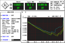
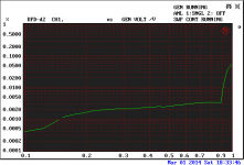
This is just before clipping (786W), in 4ohm load. Magnetic effects are predominant, with 20 amps flying around the bench (that's why the even harmonics are still dominant). Can probably get to around 0.002%-0.003% THD20 (down from the current measured 0.007%) if correctly implemented, simulates 0.001% THD20.
8 pairs of MJL onsemi bipolars, +/-90V SMPS lab supplies. There are some out of band spectral components coming from the SMPS's. Slew rate is 160V/uS.
Good enough? IMO, this is about all that can and is worth building in linear class AB. Beyond this, class D rules.
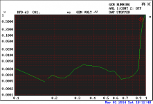
P.S. Distortion sweeps in dist.png at (bottom to top) 1KHz, 2KHz, 5KHz, 10KHz. Minimum distortions of about 0.003% at about 200W/4ohm. Halve all distortion numbers for performance into 8 ohm @~400W.
Attachments
Last edited:
Welcome Waly to the World of Big Amp Builders 🙂This is just before clipping (786W), in 4ohm load. Magnetic effects are predominant, with 20 amps flying around the bench (that's why the even harmonics are still dominant). Can probably get to around 0.002%-0.003% THD20 (down from the current measured 0.007%) if correctly implemented, simulates 0.001% THD20.
8 pairs of MJL onsemi bipolars, +/-90V SMPS lab supplies. There are some out of band spectral components coming from the SMPS's. Slew rate is 160V/uS.
Good enough? IMO, this is about all that can and is worth building in linear class AB. Beyond this, class D rules.
P.S. Distortion sweeps in dist.png at (bottom to top) 1KHz, 2KHz, 5KHz, 10KHz. Minimum distortions of about 0.003% at about 200W/4ohm. Halve all distortion numbers for performance into 8 ohm @~400W.
Are you going to share the schematic with us? Rather nice performance BTW.
What's the measuring instrument?
Welcome Waly to the World of Big Amp Builders 🙂
Are you going to share the schematic with us? Rather nice performance BTW.
What's the measuring instrument?
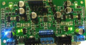
No, sharing the schematics would be a futile exercise. It's way to complicated for this place that considers the number of transistors in the gain stages as the supreme design/performance/sound quality criteria, 6 devices being the supreme ear Nirvana. The gain stages have no less than 56 SMD transistors, out of which 34 are dual devices (pnp/pnp, npn/npn, pnp/npn).
The instrument is a Rohde&Schwartz UPD in our lab. It's the AP27xx head-to- head competitor, a little less performant (higher noise floor), but much more friendly (computer and LCD display are included), and has all the options that AP adds only for big money.
Here's a photo of the gain stages board. The opamp in the center is the servo.
Attachments
Last edited:
Good enough?
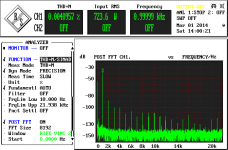
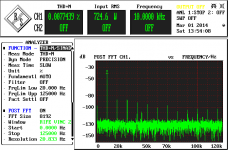
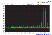
Forgot to mention that the two spectra above have the fundamental notched by 40dB. It's the standard way the UPD instrument displays the post THD+N measurement FFT.
DFD-d3 and DFD-d2 (IEC268) distortions.
And finally, the IMD 19+20KHz spectrum, before clipping (some 0.85V input), in the same 4ohm load as all along.
P.S. 4 ohm is all along resistive, haven't had so far managed to build a speaker simulation load. I think this amp would have no issues driving a 4 ohm reactive load (assuming the power supply will not sag to bad), even with the phase shifts and the here-and-there impedance dips.
Need to sleep now.
Attachments
Need to sleep now.
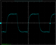
Ummm... forgot to post the step response @50KHz. Y=50V/div, X=5uS/div, quick snapshot, just before the zobel is about to explode...
Good night.
Attachments
Go on Waly! You know you want to impress us. 😀No, sharing the schematics would be a futile exercise. It's way to complicated for this place that considers the number of transistors in the gain stages as the supreme design/performance/sound quality criteria, 6 devices being the supreme ear Nirvana. The gain stages have no less than 56 SMD transistors, out of which 34 are dual devices (pnp/pnp, npn/npn, pnp/npn).
It's only moi that wants 1ppm @ 20kHz full power with 6 or less devices and some wet string. 🙂 There's loadsa gurus here who think zillion devices is the epitome of good engineering. 😱
Occam's Razor.
If you need 56 transistors, then so be it.
But if you can do with less for the same performance, that's better.
I don't think anyone's specifically anti complexity. Some here embrace it, while others have made minimalist decent sounding amplifier design an art form. See NP for example.
🙂
If you need 56 transistors, then so be it.
But if you can do with less for the same performance, that's better.
I don't think anyone's specifically anti complexity. Some here embrace it, while others have made minimalist decent sounding amplifier design an art form. See NP for example.
🙂
Number of Output
There is a limit to the THD improvement benefit there is to gained by the number of output devices, or you get to a point of diminishing returns .
It would be highly unlikely that Wally's amp would achieve 1ppm @20kHz into 8R at full power just by increasing the number of output devices.
Regards
Arthur
Occam's Razor.
If you need 56 transistors, then so be it.
But if you can do with less for the same performance, that's better.
I don't think anyone's specifically anti complexity. Some here embrace it, while others have made minimalist decent sounding amplifier design an art form. See NP for example.
🙂
I'm getting a predictable range as far as device vs. PPM.
6-8 device , both VFA/CFA - 80-200ppm (VSSA/non- beta enhanced VFA)
9-12 device , "NX" ... symasym VFA - 40-80ppm
14 device and up 😱 (full cascode blameless - hawksford leach) 2-20ppm
Simulated at 100V p-p /8R. (IPS device count -btw)
Of course you can have a 14 transistor amp (Hafler 240) that simulates
horribly ( //worse .05%) ... but some swear by that units sound. The
old leach v4.5 is also a .05% unit ... but it pleases. 😕
(leach 4.5 = no global NFB from final OP devices , "the secret" ? )
OS
As a point of reference for builders vs SIM...... I have a power amp which is around the same numbers as Waly measures..... 450-900W and it does .005% 20KHz/8R... 150v/usec etc etc. Ok. It uses.... drum roll....
30 transistors plus the last power output devices. 46 total per channel. It is 10 years old production with out benefit of newest driver and OPS devices. It is a balanced bridged configuration.
I dont use it now and the pair of mono-blocks are in storage... I use a pair of 250W CFA designs instead. Non- bridged. Fewer parts, too.
So Waly, this is a CFA group... is your design certified CFA?
Thx-RNMarsh
Last edited:
I'm getting a predictable range as far as device vs. PPM.
6-8 device , both VFA/CFA - 80-200ppm (VSSA/non- beta enhanced VFA)
9-12 device , "NX" ... symasym VFA - 40-80ppm
14 device and up 😱 (full cascode blameless - hawksford leach) 2-20ppm
Simulated at 100V p-p /8R. (IPS device count -btw)
Of course you can have a 14 transistor amp (Hafler 240) that simulates
horribly ( //worse .05%) ... but some swear by that units sound. The
old leach v4.5 is also a .05% unit ... but it pleases. 😕
(leach 4.5 = no global NFB from final OP devices , "the secret" ? )
OS
A good summary OS - I do think you need more complexity to chase low distortion - higher loop gains, more linear stages etc. My e-Amp is relatively complex with 32 devices IIRC and that does sub 10ppm and nx-Amp is a whole lot less but distortion is in the range you mention. 🙂
Last edited:
I am totally in favour of NO global feedback. BUt I would also like Low output impedance and low(ish) distortion and distortion distribution..
Last edited:
There is a limit to the THD improvement benefit there is to gained by the number of output devices, or you get to a point of diminishing returns .
It would be highly unlikely that Wally's amp would achieve 1ppm @20kHz into 8R at full power just by increasing the number of output devices.
Regards
Arthur
That's absolutely correct. Over a number of output devices, the physical dimensions start to limit the achievable (with decent stability margins) ULGF. My amp with 8 pairs is slightly under 1MHz
A good summary OS - I do think you need more complexity to chase low distortion - higher loop gains, more linear stages etc. My e-Amp is relatively complex with 32 devices IIRC and that does sub 10ppm and nx-Amp is a whole lot less but distortion is in the range you mention. 🙂
Perhaps I missed something, but I don't recall seeing any measurements on the e-Amp, are you sure those 10ppm are not a simulation result only? Besides, were those amps anywhere close to 800W/4ohm?
So Waly, this is a CFA group... is your design certified CFA?
That is classified information
 . I can disclose, though: it uses some parts with heavily copper plated ferrous leads.
Last edited:
The e-Amp results are simmed (if you read the spec sheet it says TBC). However, I'd be quite happy to put it up against anything anywhere.
I fail to see the argument you are making however since I don't recall criticizing your design.
I fail to see the argument you are making however since I don't recall criticizing your design.
There are voltage-dependant distortions and there are load-dependent distortions. An amp which has no distortion when unloaded but lots of it when loaded, has lots of the latter. On the other hand, there are amps that have high THD whether loaded or not, and the load doesn't change the distortion.
I see many amps here where the designer has gone overboard trying to correct for load-dependent distortions with more outputs, more EFs, and so on, when really it's the VAS stage generating voltage-dependent distortions that have nothing to do with the load.
Most likely everyone knows this already, but it goes with the discussion.
Why balanced in a home environment?
Good question. I have been slowly converting to balanced on my system after building Bruno Putzeys' balanced preamp.
I find that with correct implementation (pin 1 problem, anyone?) I don't have those occasional ground hum/buzz things anymore I had before when rearranging and re-connecting various parts of my system.
Could be coincidence, of course...
Jan
Could it be balanced interconnects are more tolerant of oxidized connections?
- Home
- Amplifiers
- Solid State
- CFA Topology Audio Amplifiers