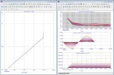
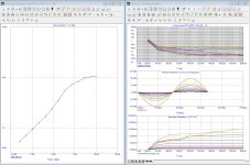
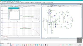
I took the liberty to sim the ~original amp in ucap and applied some modifications. First was to remove the 4.7 ohm "hum" resistor (mod 1, see stability pic). Next was a mod of the compensation: changed compensation to what strictly speaking is a change to nested feedback (mod 2). With MOS output devices this is stable and even enough so to allow a phase margin of 45 deg. Mod 3 shows what happens to 20k THD w/o the clamp diode: single digit ppm territory, good enough for most. My presentation might be a bit messy but maybe lineup can use it.
Attachments
-
 Lineup amp in ucap 3 mods.jpg63.6 KB · Views: 193
 -
 Lineup amp in ucap MOD3 THD 20k.jpg202.4 KB · Views: 183
 -
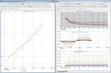 Lineup amp in ucap MOD2 THD 20k.jpg206.9 KB · Views: 118
 -
 Lineup amp in ucap orig THD 20k.jpg202.8 KB · Views: 126
 -
 Lineup amp in ucap MOD1.jpg170.1 KB · Views: 129
 -
 Lineup amp in ucap orig.jpg339.2 KB · Views: 179

Why not use the LSK489, without degeneration, if you are going to buy stuff from mouser? Unfortunately I am not able to buy from them or any other US supplier, because of outrageous taxes.
I would use it near 1mA, near the zero tempco.
I would use it near 1mA, near the zero tempco.
Long ago I bought MP311 (NPN) and MP361 (PNP) for cascoded LTP. For the cascoded VAS I intend to use MPSA18 with BD139-16, cascoded CCS BC560C with BD140-16. The only "problem" with such topology is that IMD in the audio range is too low for measurement but that's acceptable ;-)
BTW quiescent current as f(T) can be controlled with the current source topology of the LTP, but will depend on the value of Iq through the mosfets. I get this curve with current regulator diode J511 which might be OK at 20V but implies ~20W per amp at 37V.

BTW quiescent current as f(T) can be controlled with the current source topology of the LTP, but will depend on the value of Iq through the mosfets. I get this curve with current regulator diode J511 which might be OK at 20V but implies ~20W per amp at 37V.
I might try LSK489. At 1mA.Why not use the LSK489, without degeneration, if you are going to buy stuff from mouser? Unfortunately I am not able to buy from them or any other US supplier, because of outrageous taxes.
I would use it near 1mA, near the zero tempco.
I have simulated the circuit (in post #366 above) in LTspice, using the Tian probe method.
Gain Margin is about 21dB
Phase Margin is about 74 degrees
Distortion at 1watt @ 1KHz =0.000047%
Distortion at 1watt @ 20KHz = 0.0073%
If you want to use a smaller output inductor say 1.5uH the phase margin increases to about 75 degrees, gain margin stays about the same and distortion increases to 0.0084%
Am I wrong in assuming the open loop properties are only useful for the feedback loop thus the output inductor should not have influence (that is: should not be included in open loop simulation)?a smaller output inductor
True to a degree, but anything hanging off the output of the amplifier will change its loop stability, in the circuit at post #366 changing from 8R load to 4R will shift the loop gain by about 0.5db and shift the ULG from about 551KHz to about 525KHz.
Placing a 1uf capacitor across the 8R load and the loop gain drops about 1.2dB and the ULG will shift from 551KHz to about 472KHz.
Having low gain and phase margins may cause the amplifier to become unstable with difficult loudspeaker loads, the premise being if the amplifier has good margins say 21dB and 74degrees and if a difficult load is connected, if the loop gain changes then the amplifier will remain stable. This is a basic explanation, whilst I'm not an expert, this is my understanding, hopefully one of the engineers may be able to provide a better technical analysis.
All my measurements and testing is done at the feedback point and without the input filter cap.Am I wrong in assuming the open loop properties are only useful for the feedback loop thus the output inductor should not have influence (that is: should not be included in open loop simulation)?
So I do not include the Zobel.
Now I did testing with the simulator Oscilloscope.
The 20kHz squarewave did not look pretty with the circuit above here.
I might post a new circuit where the compensation is changed for a pretty 20kHz square.
LSK489 reduces the gain and increases the distortion.
So, I stick to SSM2212 input LTP.
Yes, that was expected. I suggest experimenting, listening, in practice. Because these simulations of distortion are not all there is to it.
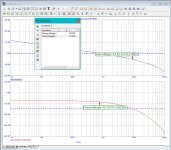
Lineup, why do you not want to do a Loop gain plot per post #354? PMA has also explained to you why you should do this. focusing on distortionn without an understanding of how the amplifier control loop is behaving is flying blind - loop gain analysis is the most important design step in any amplifier design - what is your ULGF? Phase marging, gain margin, closed loop step response, behaviour with capacitive loads etc - these are all questions that have a critical impact on amplifier performance.This is my new circuit.
Hum Breaking Resistor was removed.
DC-offset adjust was removed. As we use dual matched transistor in the input there is very low offset anyway.
TMC was set for lowest distortion. THD is now 0.00005%
View attachment 1247802
If you do the plot, people here can show you what to look for so no need to worry about that 🙂
No, you cannot exclude the zobel this way. You did not understand.So I do not include the Zobel.
Makes a difference with capacitive load. Load must be included in loopgain analysis.Am I wrong in assuming the open loop properties are only useful for the feedback loop thus the output inductor should not have influence (that is: should not be included in open loop simulation)?
I have never done a Loop Gain plot ... perhaps my software allows this ...
Evenso I do not know about ULGF, Phase margin, Gain margin and closed loop step responce.
I am sorry I know so little. And I am limited in these things.
I have to leave this to others do it with my circuit.
Makes me so sad. Maybe I should call this project off 🙁
Anyway here is the latest which fixes 20kHz squarewave.
This was done by changing the TMC.
Input filter was also changed.
Lineup, one learns a lot by constructing and measuring one's contraptions. It results in a "feel" between sims and physical circuits. Hence it's only sad you can't build what what you sim and observe its functioning on a scope and other tools. That also shows issues like wiring, ground loops, induced voltages in wiring that should be clean etc. Hence it's only sad you can't build what you sim.
You're right.True to a degree, but anything hanging off the output of the amplifier will change its loop stability, in the circuit at post #366 changing from 8R load to 4R will shift the loop gain by about 0.5db and shift the ULG from about 551KHz to about 525KHz.
Placing a 1uf capacitor across the 8R load and the loop gain drops about 1.2dB and the ULG will shift from 551KHz to about 472KHz.
Having low gain and phase margins may cause the amplifier to become unstable with difficult loudspeaker loads, the premise being if the amplifier has good margins say 21dB and 74degrees and if a difficult load is connected, if the loop gain changes then the amplifier will remain stable. This is a basic explanation, whilst I'm not an expert, this is my understanding, hopefully one of the engineers may be able to provide a better technical analysis.
Also, not only the output side but also the input side affects the loop gain. I recommend also measuring the loop gain with the input open not only short.
Generally, input has a capacitance of several tens of pF, there will be no problem.
BTW everyone
is this wrong?TMC interpret as local feedback from OPS to second stage (VAS) and global feedback nested it. When measuring global feedback, connect R12 (Compensation pier resistance) to the output side.
I have not received a reply from PMA. Bonsai is also connected to the feedback network side, what do you think?
HAYK previously measured the loop gain of only the TMC part, what do you think?
@lineup -
Don't be discouraged, please. I hope (at some point) to be even where you are today. I'd like to be able to come up with even a concept of a circuit that is interesting enough for people to give it their time and effort to improve and learn from. I've learned a tremendous amount through reading this thread.
I have no skills in PCB layout, but I am reasonably decent at assembly.
One person has proposed that someone skilled in PCB layout might assist in bringing your project forward. I disagree wholeheartedly with someone that considers it a "gas factory". It's not a shame, it's inspiring depending on one's perspective.
Once it is "tweaked", and if PCB files are made available, I will commit to building a set of boards for myself and a copy for you. I've been using this project to try and learn, and I may need some help with parts choices and/or sourcing some parts, but ... we have a pretty good community for that. It seems the perfect platform for me to learn how to measure some things in the "real world" and see how they might compare to simulations.
My own hope is that even if you don't build much currently, you might be able to at least listen to your creation.
Keep going, please. 🙂
Patrick
Hi Lineup,
I've enjoyed reading your various threads. They always seem to gather a lot of attention and discussion.
I also understand you are a designer only. I get it. Ideally, one should design and build to test and evaluate. However, the time, money and/or space needed to do this isn't available to all of us. But that doesn't mean we should abandon the hobby.
Regarding loop gain, I learn something new on this forum nearly every time I visit. I would encourage you to do a bit of research on this - there are many threads discussing it. Bonsai, myself and others have provided examples of how to perform it. It's really not that complicated.
For the Experts: Please correct me if I've missed or misstated any of the details.
I've enjoyed reading your various threads. They always seem to gather a lot of attention and discussion.
I also understand you are a designer only. I get it. Ideally, one should design and build to test and evaluate. However, the time, money and/or space needed to do this isn't available to all of us. But that doesn't mean we should abandon the hobby.
Regarding loop gain, I learn something new on this forum nearly every time I visit. I would encourage you to do a bit of research on this - there are many threads discussing it. Bonsai, myself and others have provided examples of how to perform it. It's really not that complicated.
- Run the AC sim as illustrated on the numerous examples. My post #337 shows the Tian method in LTSPice. @Bonsai's post #354 describes another method for assessing it. @ItsAllInMyHead provided a link in post #333. @PMA provided a pdf in post #335. I'm sure there are other posts with guidance that I'm missed.
- From the plot, find the frequency where gain is zero. This is the Unity Loop Gain Frequency (ULGF). This represents where the level of feedback to reduce open loop gain has reached zero.
- Now, find out how far down the 180 degree crossing. The minimum for stability is often quoted as 10 db and 45 degrees down. However, as others have stated, having a bit of cushion helps. I think most designers would like to see at least 15 db and 60 degrees, if not 20db and 70 degrees. Look at the plot in my example at post #337. This first cursor is the ULGF (@Bonsai provided guidance on this in post #358). You can see it crosses around 1MHz. You can see that the second cursor is positioned where the phase has dropped to -180 degrees. The difference between the cursors is your gain and phase margin.
For the Experts: Please correct me if I've missed or misstated any of the details.
How are you plotting the frequency response of your amp?I have never done a Loop Gain plot ... perhaps my software allows this ...
Evenso I do not know about ULGF, Phase margin, Gain margin and closed loop step responce.
I am sorry I know so little. And I am limited in these things.
I have to leave this to others do it with my circuit.
Makes me so sad. Maybe I should call this project off 🙁
Anyway here is the latest which fixes 20kHz squarewave.
This was done by changing the TMC.
Input filter was also changed.
View attachment 1247850
- Home
- Amplifiers
- Solid State
- Cello One. Good Amplifier 15 Watt with TMC and Laterals