Barry worked hard to create well designed circuits that added little to no noise and did not add any color of their own. Cadac studio consoles were one of his many projects. He died before digital had become practical. He was an analog giant. I for one would like to learn more about him and his work.
Assuming that the PCB that I receive this week works, I would have no problem making the gerbers or even fabbed PCBs available to anyone that wants them.
Assuming that the PCB that I receive this week works, I would have no problem making the gerbers or even fabbed PCBs available to anyone that wants them.
I noticed that. It seemed to me if it wasn't designed with the same goals in mind and didn't behave like a Palette, then it wasn't a Palette.Here is a version done with state variable filters. The problem with other designs presented is that the 'Q' did not match that of the Cello.
Great job, Carl.Carl_Huff said:Unfortunately a stereo version contains lots of opamps. You would want to use quiet ones such as the LM4562. I have a stereo version using all thru hole parts in the works. The PCB is out for fab now. The PCB for both channels fits into a 1U chassis.
I just briefly looked at the schematic today and that is some dedication.
I wonder if four channel opamps might make it simpler? What is your opinion of components on both outer layers of an FR4, with a dedicated ground layer?
"I wonder if four channel opamps might make it simpler?"
If we were to use quad packaged opamps our choices of opamps quickly diminishes. Builders usually have a favorite dual that they can pop in.
"What is your opinion of components on both outer layers of an FR4, with a dedicated ground layer?"
That would be a more expensive board for sure. And what's worse is that we would have to go all surface mount parts. Surface mount takes the fun out it for me. I prefer good'ol thru hole parts.
Two channel EQ similar to the classic Cello
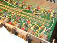
The PCBs are back from fab. Altho this is not a PIC of a PCB, this view affords more detail.
The PCB looks exactly like this. Lots of resistors!
Are enough people interested in this for me to document it?
If 'yes', do I put those details in this thread or start a new one??
The PCBs are back from fab. Altho this is not a PIC of a PCB, this view affords more detail.
The PCB looks exactly like this. Lots of resistors!
Are enough people interested in this for me to document it?
If 'yes', do I put those details in this thread or start a new one??
Attachments

Make it for Sale 🙂
Would Be Good to See it On Sale , it's an incredible view to have it and feel the clicks of Knobs
Would Be Good to See it On Sale , it's an incredible view to have it and feel the clicks of Knobs
I owned one of the original Cello Audio Palettes. Amazing piece off gear and the product I most regret selling (by a considerable margin). Part of what made it a great product was there beautiful feel off the controls. Have you thought about how you would implement them?
I had mine set up in a custom built coffee table so that it was easily at hand at the listening position. This, of course, required long cables from my sources (side of room) and to the amps (monoblocks next to speakers). I used Cello Strings for this, which were balanced cables using the funky Fischer connectors.
I think balanced connections would be desirable in a clone because of the long cable lengths, even if implemented with separate active circuits.
I'm definitely interested if you decide to make the boards available.
XLR is a Must for long Wires
I agree that it has to go in seating area and for this reason only possible with balanced XLR in-out
I agree that it has to go in seating area and for this reason only possible with balanced XLR in-out
I am using Alps linear pots with a center detent for the prototype.
I invite others to improve upon that. I am open to suggestion.
I invite others to improve upon that. I am open to suggestion.
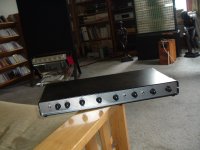
My version
Two pics of my Palette Preamplifier version.
Used the original schematic but only built-up the equalizer portion (no additonal amplification, balanced I or O) in a separate (remote) box with a 20ft interconnecting umbilical cable.
The other end of the cable is "Integrated" into my version of the Cello Encore preamp (it's actually a line stage). In addition to the 6 frequency controls on the remote (plus switches on two of the pots to vary the "base" frequency slightly), I added two (Left / Right) gain trim pots (+/- 3db or so) and an "in/out" switch so I can instantly compare the "equalized" to "un-equalized" signals - from the listening position.
Also attached a block diagram of the original Palette - drawn by Paul Jayson in 1985. I marked it up to show some missing items and some totals for the amplifier modules.
There never was a technical/service manual for the Palette. Any product drawings Cello made/used were intended for MANUFACTURING purposes. Never worried about "aftermarket repair". This was not unsual; found that the same was true for at least Levinson and Krell.
For all of their products there were schematics/parts placement for the individual PC boards, but any interconnections between boards/modules/etc were described by "from/to" wiring lists - in addition to any necessary drawings showing where any parts/devices/PC boards placement, like on the front, bottom and rear panels.
Charles
Attachments
Last edited:
The PCBs are back from fab. Altho this is not a PIC of a PCB, this view affords more detail.
The PCB looks exactly like this. Lots of resistors!
Are enough people interested in this for me to document it?
If 'yes', do I put those details in this thread or start a new one??
Very interested !
Regards
Anders
Barry worked hard to create well designed circuits that added little to no noise and did not add any color of their own. Cadac studio consoles were one of his many projects. He died before digital had become practical. He was an analog giant. I for one would like to learn more about him and his work.
Assuming that the PCB that I receive this week works, I would have no problem making the gerbers or even fabbed PCBs available to anyone that wants them.
Huh.
Well, here's hoping I don't jinx myself: Yr 'Umble Narrtr is working on a Cello-like of my own, with a twist: variable center frequencies plus or minus an octave from spec on a seven position switch. For example, the third band will contain 600 Hz as per the original spec, but also 300, 400, 500, 800, 1000, and 1200 Hz, whereas the 2000 Hz band would have 1000, 1200, 1600, 2000, 2400, 3200, and 4000 Hz. Note the overlap: if the 600 Hz band is tweaking 300 Hz and you also want to touch up 1200 then the 2000 Hz section can be enlisted to help.
Why a switch instead of a control? This one will have one set of controls for left and right so a control driving a state variable filter would need four gangs for two channels, and those things in anything but carbon track (ick) are rarer than hen's teeth. So it's gyrator time for this little puppy, although we'll avoid the standard one op amp gyrator which has a host of problems such as noise. Instead we'll use the Antoniou architecture which offers better performance at the price of requiring two gain stages rather than one. Since opamps are relatively cheap, it's no big deal.
The astute observer would note tuning only the inductor means the Q changes drastically across the range. However, the frequency selection switch can also choose a different capacitor to go with the "inductor" (I have a possible circuit on my other computer but the margin of this post is too narrow to contain the proof). Also, since the various frequency sections of the Cello have different Qs and +- gains, the individual tuned sections can be arranged to merge smoothly from one band to another. Doing the sums involves tedious and fiddly arithmetic, however, so I bunged together a spreadsheet to help with the number crunching. It's an unpretty piece of Excel and documentation is sorely lacking, but it serves my purposes.
Given my usual glacial pace of progress I expect this might make an appearance late next year, fair winds and following seas permitting.
Oh, right, the motivation for all this: the EQ is in a distinct box from the rest of the preamp, with a 25 foot (8 metre) cable running to the EQ which will sit beside the listening chair. And it'll be quasi-balanced, with the signal on the hot, circuit ground to neutral, and both lines going to a differential amplifier so it can cancel any interference. Here's a tiny subtlety: hot might want to feed the inverting input to avoid common-mode distortion. Since interference should be relatively small, common-mode interference on the zero-volt send to the non-inverting input will be presented at a lower level than the main signal on the inverting input and thus be undistorted so it can be properly cancelled. I had to keep a gimlet eye on power issues, avoiding ground loops by powering the EQ from the preamp and waving away line impedance via local regulation. Even at +-12 volts any competent opamp has more than enough dynamic range to completely saturate anything downstream.
Anyway, this is all speculative until the soldering iron warms up so I thought y'all might be amused at the presumption. What will the thing sound like? As I tell my hiking partner before we embark on a tough one, it will be a Voyage Of Discovery. It's a 49-49 proposition: either really good or truly lousy, with a small chance of being somewhere in between.
Haha! I wonder how many would get this: "but the margin of this post is too narrow to contain the proof"
Neat.
Jan
Neat.
Jan
Two pics of my Palette Preamplifier version.
Used the original schematic but only built-up the equalizer portion (no additonal amplification, balanced I or O) in a separate (remote) box with a 20ft interconnecting umbilical cable.
The other end of the cable is "Integrated" into my version of the Cello Encore preamp (it's actually a line stage). In addition to the 6 frequency controls on the remote (plus switches on two of the pots to vary the "base" frequency slightly), I added two (Left / Right) gain trim pots (+/- 3db or so) and an "in/out" switch so I can instantly compare the "equalized" to "un-equalized" signals - from the listening position.
Also attached a block diagram of the original Palette - drawn by Paul Jayson in 1985. I marked it up to show some missing items and some totals for the amplifier modules.
There never was a technical/service manual for the Palette. Any product drawings Cello made/used were intended for MANUFACTURING purposes. Never worried about "aftermarket repair". This was not unsual; found that the same was true for at least Levinson and Krell.
For all of their products there were schematics/parts placement for the individual PC boards, but any interconnections between boards/modules/etc were described by "from/to" wiring lists - in addition to any necessary drawings showing where any parts/devices/PC boards placement, like on the front, bottom and rear panels.
Charles
Nice work Charles! When I wore a younger man's cloth I interviewed Mark Levinson at a local dealer show (a big dealer ;-) and he showed me the internals of a Palette. IIRC the controls were regular potmeters but there was a separate indent construction that gave the impression they were switched controls. Is my recollection correct?
Jan
Hi Jan,
And how did the younger mans clothes fit? As well as today's duds? Same size???
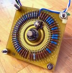
The original Palette had Levinson's "signature" 52? position, single pole devices. The mechanics of which were used in a number of his products including volume and balance controls. The base plate had "stops" on it to determine the actual number of positions for a particular application.
As has been mentioned, Colangelo took Burwens original Op Amp based design and implemented it with discrete components. The Palette Preamp used Op Amps (627's with 633 buffers) and used potentiometers without a center detent. I had a few of these boards, populated and unpopulated. The Sefernic(sp?) potentometers on the populated boards seemed to get noisy over time.
My first look inside the original Palette at a Mcintosh / Levinson dealer (late 1980's, in Hartford CT) left me totally astonished!!
Charles
And how did the younger mans clothes fit? As well as today's duds? Same size???
The original Palette had Levinson's "signature" 52? position, single pole devices. The mechanics of which were used in a number of his products including volume and balance controls. The base plate had "stops" on it to determine the actual number of positions for a particular application.
As has been mentioned, Colangelo took Burwens original Op Amp based design and implemented it with discrete components. The Palette Preamp used Op Amps (627's with 633 buffers) and used potentiometers without a center detent. I had a few of these boards, populated and unpopulated. The Sefernic(sp?) potentometers on the populated boards seemed to get noisy over time.
My first look inside the original Palette at a Mcintosh / Levinson dealer (late 1980's, in Hartford CT) left me totally astonished!!
Charles
Last edited:
Somewhat over 30 years ago I had the opportunity to work with Dick Burwen for a time at Copley Controls, and got the full basement system demo which of course included what was probably the original prototype of the Audio Palette. He explained that the center frequencies and boost/cut values were very carefully determined through listening tests, etc.
I do remember that part of the demo involved playing a piece of music where panning certain controls on the Palette resulted in quite a change in the placement of certain instruments in the sound stage. I was extremely surprised to say the least. I don't remember a lot of details this long after the fact. Just wanted to mention that there was nothing arbitrary at all about the philosophy behind the design.
I was a purist (call that naive?) and didn't believe in any EQ or tone control use at the time. These days I use a MiniDSP SHD and Dirac3 for room/system EQ, somewhere along the way I changed my mind.. LOL
Hi Jan,
And how did the younger mans clothes fit? As well as today's duds? Same size???
Actually yes same size. Again, after some deviations upwards ;-)
And it seems my recollection was flawed, there actually appear to be switched attenuators as potmeters.
Jan
Attachments
Last edited:
Somewhat over 30 years ago I had the opportunity to work with Dick Burwen for a time at Copley Controls, and got the full basement system demo which of course included what was probably the original prototype of the Audio Palette. He explained that the center frequencies and boost/cut values were very carefully determined through listening tests, etc.
I do remember that part of the demo involved playing a piece of music where panning certain controls on the Palette resulted in quite a change in the placement of certain instruments in the sound stage. I was extremely surprised to say the least. I don't remember a lot of details this long after the fact. Just wanted to mention that there was nothing arbitrary at all about the philosophy behind the design.
I was a purist (call that naive?) at the time and didn't believe in any EQ or tone control use at the time. These days I use a MiniDSP SHD and Dirac3 for room/system EQ, somewhere along the way I changed my mind.. LOL
If anything said above lent the impression I thought Richard Burwen had chosen his parameters arbitrarily then I was unclear. He did a damned good job on the Palette, and I learned a lot simply from musing over how the controls work.
Given that, during my pro audio time, fixed-frequency mixing consoles left me wishing I could scooch the midrange control just a little over when dealing with a kank in a snare drum, for example, or fill a bit of low mid into a guitar amp mike feed. Since we're dealing with an entire mix, the section frequency selection is more intended to zero in on an area thereof with a minimum number of sections involved (each one will have a defeat switch; those are trivial to add), with no more than two or three frequency sections active at a time for most recordings. Anything further risks getting into territory of dubious taste.
As far as EQ, I feel ya: for now I have a parametric wired in before the crossover to deal with a room boom (-5 db @ 70Hz, 1/6 octave) and a bit of tweeter spitchiness at 12 kHz. Once the tweeter's sorted the thing might migrate to the subwoofer feed so the rest of the channels are left alone.
- Home
- Source & Line
- Analog Line Level
- Cello Audio Palette