The differences in the new, old and currentlly available capacitor values are insignificant.
Such small differences are inaudible.
The currently available MKPs from Wilmslow Audio include 2.2uF; 3.3uF and 3.9uF - these may be substituted directly for the lower values you have stated
Fot the 24/25uF, you may wire a 2.2uF in parallel with a 22uF.
Such small differences are inaudible.
The currently available MKPs from Wilmslow Audio include 2.2uF; 3.3uF and 3.9uF - these may be substituted directly for the lower values you have stated
Fot the 24/25uF, you may wire a 2.2uF in parallel with a 22uF.
To put it simply, provided the replacement capacitor values are within plus or minus 10% of the original values, you have nothing to worry about!
T.S. Elliot said:“Between the idea
And the reality
Between the motion
And the act
Falls the Shadow”
😀
The shadow is fear, uncertainty and doubt, of course.
That's what keeps this forum spinning!Originally posted by Douglas Adams
"We demand rigidly defined areas of doubt and uncertainty!"

The Inductors in the 25 crossover.
I will be very surprised if all those Inductor values posted in this thread are correct , and if they are then two of them seem to have been inadvertently exchanged for their relative circuit locations.
There is a Schematic available for the Celestion 25 crossover - at least two forum members have it though neither has posted it in the thread, but if you ask them they might post it here, or they might post the values of the inductors at least.
Read posts #3 and #5 in the Celestion 66 thread here:
Celestion Ditton 66
and message to those two members.
Regards ,
Last edited:
I'm not sure that helps, my friend. You have just sown FUD here without saying what might be wrong in the schematic. We are only talking about swapping out some capacitors. In fact the only one worth doing, IMO, is the 24uF NP.
This schematic is the best we've got with the caveat that C5 is 2uF. And I see the LC shunt. But I'd be checking all this as I do the rebuild.
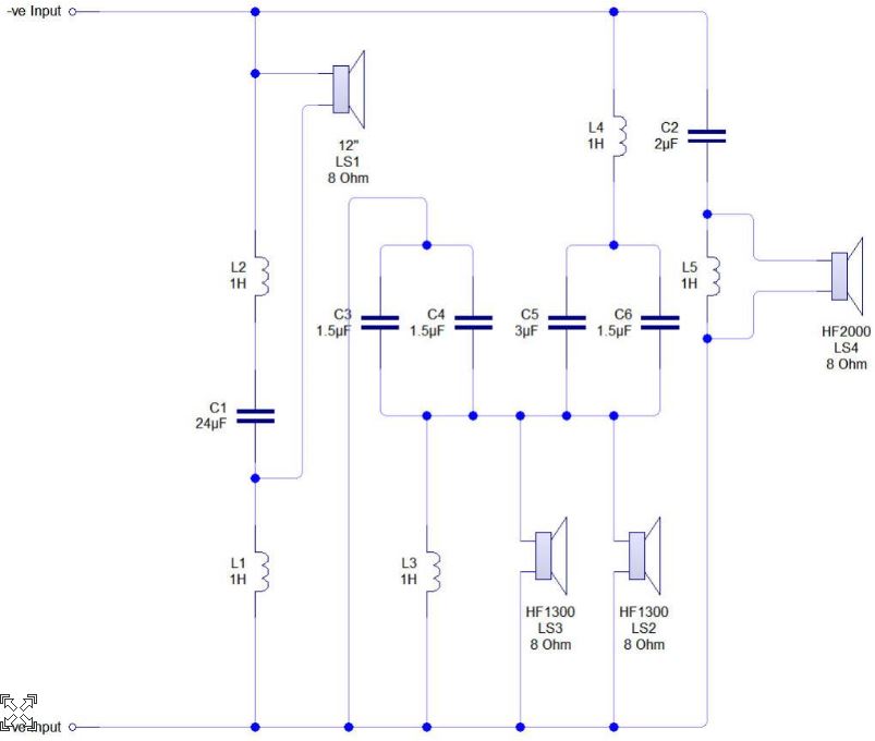
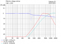
I've run the sim in a roughish way, and that 24uF/2.4mH (iron core) shunt must have resistance. We think 8 ohms. If it didn't, the speaker wouldn't work as the sim shows. Nothing stopping a resistance measurement if it's a concern anyway. It's actually a vague bit of 4dB bafflestep.
People agonise over whether 2uF can be changed to a more available 2.2uF value, for instance. Are you going to hear it? I doubt it. Might sound better if anything... 😀
This schematic is the best we've got with the caveat that C5 is 2uF. And I see the LC shunt. But I'd be checking all this as I do the rebuild.
I've run the sim in a roughish way, and that 24uF/2.4mH (iron core) shunt must have resistance. We think 8 ohms. If it didn't, the speaker wouldn't work as the sim shows. Nothing stopping a resistance measurement if it's a concern anyway. It's actually a vague bit of 4dB bafflestep.
People agonise over whether 2uF can be changed to a more available 2.2uF value, for instance. Are you going to hear it? I doubt it. Might sound better if anything... 😀
Attachments
Last edited:
I will be very surprised if all those Inductor values posted in this thread are correct.
The inductor values are unknown since the originator of the crossover circuit diagram did not have an inductance meter.
The 1H markings on the crossover diagram are only there by default.
P.S. I shall look with interest at the Celestion Ditton 66 thread which you have brought to our attention.
In my mind, and sim, I was including Dave's schematic too:
But we are only interested in the capacitors here.
Just my opinion, but I think far too much agonising went into the LONG Ditton 66 thread. Who's to say that Celestion got everything perfect? Do you really need to pay inflated prices for original replacement drivers? I always thought the Ditton 15XR was poor. And, if I am critical of an otherwise good speaker, my Ditton 44 have more midrange cone breakup than I like.
Last edited:
In my mind, and sim, I was including Dave's schematic too.
I apologise to alan-1-b for forgetting about that schematic!

several points
Hi Galu ,
There is no need to apologize , as I did not fully describe my thinking , however I do appreciate your graciousness , and I thank you for that.
Hi system7 ,
as you stated:
"Just my opinion, but I think far too much agonising went into the LONG Ditton 66 thread. Who's to say that Celestion got everything perfect? Do you really need to pay inflated prices for original replacement drivers? I always thought the Ditton 15XR was poor. And, if I am critical of an otherwise good speaker, my Ditton 44 have more midrange cone breakup than I like."
I reply:
There are at least three Celestion 66 threads in this Forum, and perhaps four ... I have forgotten how may I have seen.
In the longest one , and to which I contributed a lot , yes there is "far too much agonising" -{ including by myself ! }- however some people do agonize and I attempt to be helpful within the limits I have , and that means accommodating their agonizing whilst attempting to explain the things that seem to matter to them.
The Celestion 66 thread I posted the Link to in this thread is not that very long thread , it is a very short thread , and really only the two posts I listed are relevant to my post in this thread.
When I first listened to music through a Ditton 15XR I also thought they were poor , and I did not understand why , given the good reputation that Celestion had then , however I have since found over many years of listening to Music recordings , with other people that there are at least two , and likely three or four , DIFFERENT ways the human brain interprets musical performance when heard through various loudspeakers of substantially different design.
After learning about drivers and crossovers I identified what I did not like about Ditton 15XR and why , however for people whose hearing-brain priority is different to mine I can understand why they like 15XR.
Similar is the case for the legendary and controversial LS3/5a design - it seems to be a Love-it-or-Hate-it design , however I can hear things through it that I realize are the ear-brain audio priorities for some listeners , though I do not like LS3/5a for how I hear performance of music -{ and that is completely irrespective of its no low Bass and slightly accentuated upper Bass , and there are some loudspeakers designed with similar and some almost identical audible characteristics to LS3/5a which have extended low Bass , albeit requiring 3-way crossover and 3 drivers }.
Also: I am not familiar with many current use acronyms , thus please spell out what "FUD" is ?
In General:
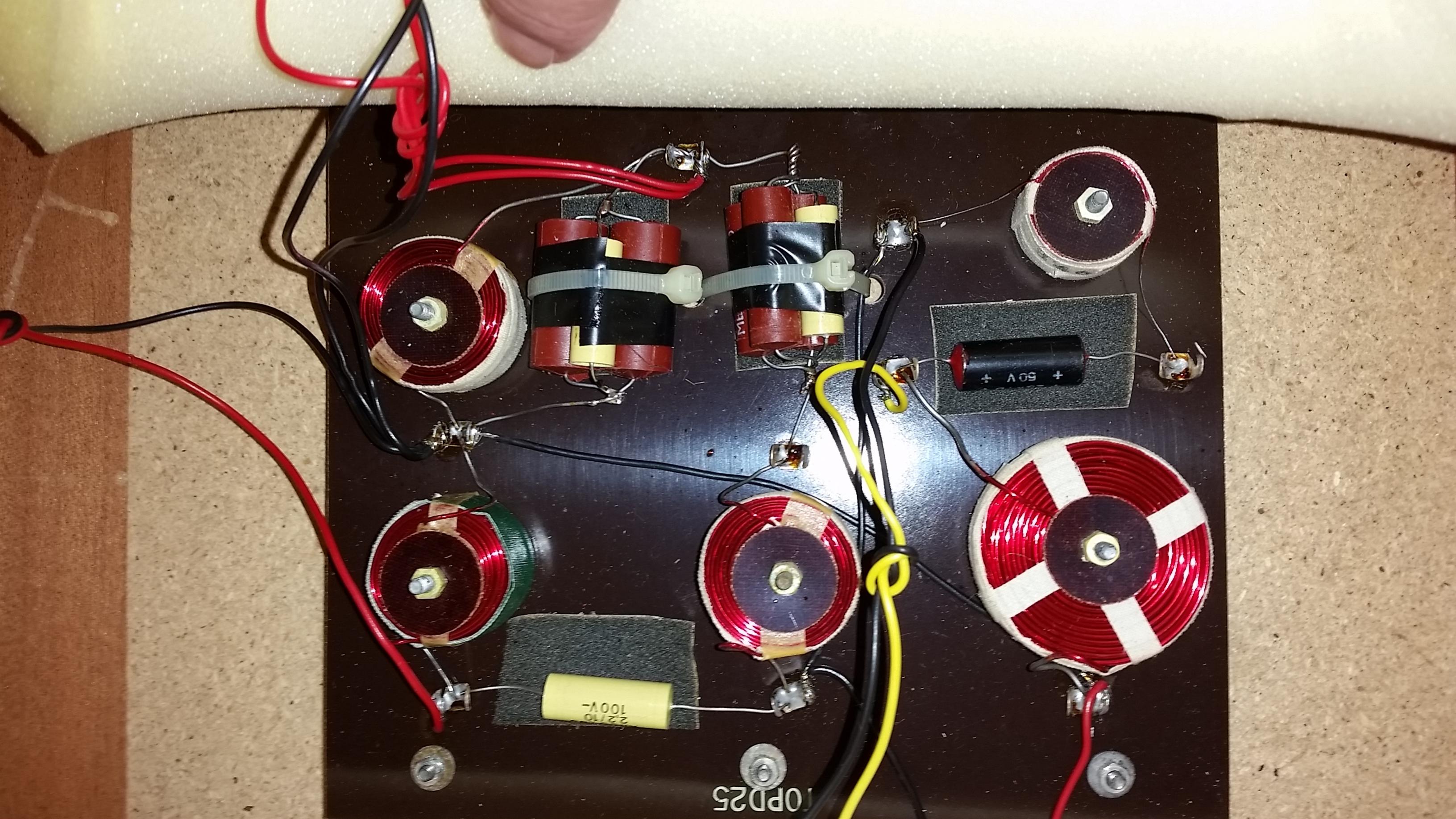
To be able to contribute anything useful to this thread I need the inductance values confirmed.
I do not doubt that "dave" is sincere , and he certainly seems to be in the various posts I have read of his in other threads , however sometimes people can have been given a mistake in information -{ that has happened to me }- thus it will be good to have the inductors confirmed if possible.
I will explain why after I have them confirmed , but for now if someone with a Multimeter will examine a 25 crossover and find which inductor on the board is connected to which capacitors and drivers , and how connected , and measure the DC resistances of all the inductors -{ with the capacitors and the drivers disconnected }- and post all that here , then we can solve at least one of the ongoing points of discussion in this thread , that being about the 24uF capacitor , and for that we need to know the DC resistance of the inductor it is directly connected in Series with in that two-components' Shunt across the woofer.
Also useful will be: measure the DC resistances of all the drivers while they are disconnected from the crossover, and post the results here.
The woofer is probably a Nominal 4 ohm , with a DC resistance a little above 3 ohms , and the HF2000 is probably a Nominal 4 ohm with a DC resistance a little above 3 ohms but there might have been a Nominal 8 ohm version of that tweeter ?
HF1300 was available in all three of Nominal: 4 ohm , 8 ohm , 16 ohm.
It may be either the 8 ohm or the 16 ohm versions that were used in the 25.
Regards ,
Hi Galu ,
There is no need to apologize , as I did not fully describe my thinking , however I do appreciate your graciousness , and I thank you for that.
Hi system7 ,
as you stated:
"Just my opinion, but I think far too much agonising went into the LONG Ditton 66 thread. Who's to say that Celestion got everything perfect? Do you really need to pay inflated prices for original replacement drivers? I always thought the Ditton 15XR was poor. And, if I am critical of an otherwise good speaker, my Ditton 44 have more midrange cone breakup than I like."
I reply:
There are at least three Celestion 66 threads in this Forum, and perhaps four ... I have forgotten how may I have seen.
In the longest one , and to which I contributed a lot , yes there is "far too much agonising" -{ including by myself ! }- however some people do agonize and I attempt to be helpful within the limits I have , and that means accommodating their agonizing whilst attempting to explain the things that seem to matter to them.
The Celestion 66 thread I posted the Link to in this thread is not that very long thread , it is a very short thread , and really only the two posts I listed are relevant to my post in this thread.
When I first listened to music through a Ditton 15XR I also thought they were poor , and I did not understand why , given the good reputation that Celestion had then , however I have since found over many years of listening to Music recordings , with other people that there are at least two , and likely three or four , DIFFERENT ways the human brain interprets musical performance when heard through various loudspeakers of substantially different design.
After learning about drivers and crossovers I identified what I did not like about Ditton 15XR and why , however for people whose hearing-brain priority is different to mine I can understand why they like 15XR.
Similar is the case for the legendary and controversial LS3/5a design - it seems to be a Love-it-or-Hate-it design , however I can hear things through it that I realize are the ear-brain audio priorities for some listeners , though I do not like LS3/5a for how I hear performance of music -{ and that is completely irrespective of its no low Bass and slightly accentuated upper Bass , and there are some loudspeakers designed with similar and some almost identical audible characteristics to LS3/5a which have extended low Bass , albeit requiring 3-way crossover and 3 drivers }.
Also: I am not familiar with many current use acronyms , thus please spell out what "FUD" is ?
In General:
To be able to contribute anything useful to this thread I need the inductance values confirmed.
I do not doubt that "dave" is sincere , and he certainly seems to be in the various posts I have read of his in other threads , however sometimes people can have been given a mistake in information -{ that has happened to me }- thus it will be good to have the inductors confirmed if possible.
I will explain why after I have them confirmed , but for now if someone with a Multimeter will examine a 25 crossover and find which inductor on the board is connected to which capacitors and drivers , and how connected , and measure the DC resistances of all the inductors -{ with the capacitors and the drivers disconnected }- and post all that here , then we can solve at least one of the ongoing points of discussion in this thread , that being about the 24uF capacitor , and for that we need to know the DC resistance of the inductor it is directly connected in Series with in that two-components' Shunt across the woofer.
Also useful will be: measure the DC resistances of all the drivers while they are disconnected from the crossover, and post the results here.
The woofer is probably a Nominal 4 ohm , with a DC resistance a little above 3 ohms , and the HF2000 is probably a Nominal 4 ohm with a DC resistance a little above 3 ohms but there might have been a Nominal 8 ohm version of that tweeter ?
HF1300 was available in all three of Nominal: 4 ohm , 8 ohm , 16 ohm.
It may be either the 8 ohm or the 16 ohm versions that were used in the 25.
Regards ,
Last edited:
Steve, there's a lovely pair for sale in Lockleaze, Bristol on Gumtree...you could pop over and pick them up just to clarify this muddle for us.
Hi Alan!Read posts #3 and #5 in the Celestion 66 thread here:
Celestion Ditton 66
and message to those two members.
Thanks for pointing out possible sources for the Ditton 25 crossover schematic.
Could this culminate in a conclusion to the crossover quandry?!
I will be very surprised if all those Inductor values posted in this thread are correct , and if they are then two of them seem to have been inadvertently exchanged for their relative circuit locations.
There is a Schematic available for the Celestion 25 crossover - at least two forum members have it though neither has posted it in the thread, but if you ask them they might post it here, or they might post the values of the inductors at least.
Read posts #3 and #5 in the Celestion 66 thread here:
Celestion Ditton 66
and message to those two members.
Regards ,
A big thanks for this ... I've just messaged them
Steve, there's a lovely pair for sale in Lockleaze, Bristol on Gumtree...you could pop over and pick them up just to clarify this muddle for us.
£350 .. Just pop your hand in your pocket while your popping over there 🙂
Maybe a bit late, but i found another map on my HD.
dave
Sorry Dave I didn't thank you for this .. It is the confirmation schematic I was looking for ..
I think I shall be using these values .. Which some are slightly lower than the values of the caps I found in the speakers at the mo ... Unless some one tells me that's a terrible idea ?
The only difference between the capacitor values in the two versions of the crossover is that of the one associated with the supertweeter.
In Dave's it is a 3.0uF and in Steve's it is a 2.0uF.
A 2.2uF replacement will probably be fine, but you can always experiment by paralleling it with a 1.0uF to see what difference (if any) that makes.
In Dave's it is a 3.0uF and in Steve's it is a 2.0uF.
A 2.2uF replacement will probably be fine, but you can always experiment by paralleling it with a 1.0uF to see what difference (if any) that makes.
Let me stress again:some are slightly lower than the values of the caps I found in the speakers at the mo ...
Just make sure the replacement capacitor values are within plus or minus 10% of the values found in your speakers at the moment - simple!
If you choose to experiment with the value of the supertweeter capacitor, then see my previous post.
this is the differenceThere is a difference between the newer pair and the Values from previous posts about 25's ..
my newer pair values seen = 25 uF 2.2 uF 3.2 uF 3.7 uF
and an old thread schematic = 24uF 2 uF 3uF 3.5 uF
The caps in the older thread looked like they were the older Electrolytic type
Any Ideas which values I should go with ?
This is my answer!Just make sure the replacement capacitor values are within plus or minus 10% of the values found in your speakers at the moment!
- Status
- Not open for further replies.
- Home
- Loudspeakers
- Multi-Way
- Celestion Ditton 25 help needed