The active regulators will be based on LT1085 and located as closed as possible to the mechanism. I decided to use those chips to simplify the construction, unless somebody has better suggestion.😉 Passive filtering scheme is based on Kusunoki DAC http://www.homestead.com/whaan/files/tda1543_dac.jpg
I used total of 33,000uF capacitance per section.
I used total of 33,000uF capacitance per section.
Attachments

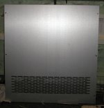
Player looks great! How did you make the ventilation grating for each of the sides? I like how you made good use of the HD angled extensions.
--
Brian
--
Brian
BrianGT said:How did you make the ventilation grating for each of the sides?
I just bought a panel like this from a local surpluss outlet and cut it to the size.😉 When making a unit like that, there is so many decisions to make that the final product is quite different from what you might think about in the beginning. And I'm just a one person committee.😉
I was thinking about experimenting with different PS configurations and setups, but when I figured out how much space I had and what parts ( because of that) I would be able to use, there was not much choice in the end. 😉 I've got way better caps but I'm not able to use them because of space restrictions. I still need a space in a second tower for DAC's PS. And getting rid of SPDIF is probably a better choice than going all way out with exotic caps. One thing I know for sure: I need a separate, split bobbin transformer for every stage.🙂
Attachments
You had me confused with those ventilation slits. It makes more sense now. I thought you went out and bought more tools. 🙂
It looks very professional looking. How did you decide exactly on the dimensions of the two side pods? Did you base them on the width of the transformers?
I like this picture here:

It would have been nice if the front panel was half as high, and the spikes could be seen from the front. Nevertheless, I really like the quality and the industrial look of your chassis. Congratulations on the good work. Now your task is to make it sound as good as it looks, which seems like a much more difficult task.
Good luck!
--
Brian
It looks very professional looking. How did you decide exactly on the dimensions of the two side pods? Did you base them on the width of the transformers?
I like this picture here:
It would have been nice if the front panel was half as high, and the spikes could be seen from the front. Nevertheless, I really like the quality and the industrial look of your chassis. Congratulations on the good work. Now your task is to make it sound as good as it looks, which seems like a much more difficult task.
Good luck!
--
Brian
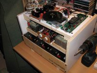
Currently I prefer to do as little work as possible, so the side pods size was determined both by the transformers size and by what was available. Since the extrusions come in half inch size variaton I settled on 4". It also allowed a nice gap at the top for vents. Initially I thought about connecting HD angles together, but leaving the spaces between them made the whole thing look better.
The front panel size is determined by the display PCB which comes with a transport. I didn't want to go as far as designing a new one.😉
The front panel size is determined by the display PCB which comes with a transport. I didn't want to go as far as designing a new one.😉
materials sound good
using composite construction (aluminum/phenolic) is a definite plus. i was wondering if you would damp some of the thinner panels though, such as the extrusions of the power supply towers. they appear like they might still be slighty ringy, and might induce some colorations thru modulation of the power supply electronics.
i was thinking of making a composite platform for some components using a MDF slab and copper and/or aluminum panels and constrained layer damping using EAR material. would be a lot more inert than the traditional aluminum/steel chassis methinks, and copper is one of the best shields available (and supposedly one of the best-sounding). i wonder if maybe a fountainhead slab would be even better, those fake stone materials they use for kitchen countertops... or acrylic...
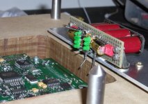
No sound yet. So far I completed transports PS and start doing connections.
As to damping PS housing, one way I wanted to avoid the vibrations was to use angles which not form large panels. Also when space permits I'll use damping sheets inside.
Check this link about reducing vibrations in equpment support: http://www.stereophile.com/showarchives.cgi?204
As to damping PS housing, one way I wanted to avoid the vibrations was to use angles which not form large panels. Also when space permits I'll use damping sheets inside.
Check this link about reducing vibrations in equpment support: http://www.stereophile.com/showarchives.cgi?204
Attachments

tbla,
Since you've built it, how important is delay of 9V supply to 5V one? If my supplies are separate but exactly the same would it work OK, or should I make it somehow come later (9V).
Since you've built it, how important is delay of 9V supply to 5V one? If my supplies are separate but exactly the same would it work OK, or should I make it somehow come later (9V).
cdpro2
hi peter !
well, i haven't had sound from my project yet - but as i understand it, the delay is important. i've heard from others too.
all cdpro2-projects i've seen, do have delay circuit.....
my project : cdpro2, 4 x tda1541as1 in parallel, no digitalfilter, I2S-connection, analog : ala borbely/pass, analogfilter : i'm not shure yet but perhaps 6db with cutoff freq arround 10khz......
all power supplys are walt jung superregulators - lots of them actually.
for the moment i use a naim cdi-player......with atc scm100sl and atc sia 2-150 amp - loud and clean hehehe
regards
troels
Hey fella,
Very awesome and sophisticated project, nice to see and hear this until the end, but I got some idea to put in this project (if you don't mind), why don't you try to operate this machine with supply from sealed acid batteries, I've build the DAC operated with this method and you must know what this verdict, operated continues for 5-8 hours without any problem, perhaps this idea it's too late but with the project like this I can't resist anymore...
Long Live DIY.........
Best regards,
Datoek Jacques
Some claim that battery operation is not that good.😉
http://www.audioasylum.com/audio/tweaks/messages/48064.html
http://www.audioasylum.com/audio/tweaks/messages/48064.html
It's still not to late for battery because supply for DAC is not done.😉 How would you compare the sound from battery and regulator (and what type of regulator).
My regulator from my DAC is stiil LM-type hard to find LT-series, the sound is analog-like, smooth and not fatigue, try this you'll be notice the different.
Btw: by this, at least your player not the same as ML
Datoek Cohen
Btw: by this, at least your player not the same as ML
Datoek Cohen
hi peter...
about the walt jung regulators check this :
http://www.diyaudio.com/forums/showthread.php?goto=newpost&threadid=1437
alw is the one to ask about regulators.
i haven't got to the delay yet, but as soon as i get to it i will let you know.
best regards,
troels
about the walt jung regulators check this :
http://www.diyaudio.com/forums/showthread.php?goto=newpost&threadid=1437
alw is the one to ask about regulators.
i haven't got to the delay yet, but as soon as i get to it i will let you know.
best regards,
troels
peter,
maybe try using a mosfet as the regulator, then you can control the higher voltages being turned on and off (delayed) with the 5v logic and solve the regulator issue at the same time.
maybe try using a mosfet as the regulator, then you can control the higher voltages being turned on and off (delayed) with the 5v logic and solve the regulator issue at the same time.
- Status
- Not open for further replies.
- Home
- Source & Line
- Digital Source
- CD PRO 2 - The making of a high end CD Transport