Do you mean they have added complexity to the output stage in order to increase the separation because they have used two DAC chips per channel?
That's interesting, a design trade-off, they must have gained something significant from using two WM8740s per channel in order to justify the added complexity in the output stage.
That's interesting, a design trade-off, they must have gained something significant from using two WM8740s per channel in order to justify the added complexity in the output stage.
The improvement over a single WM8740 per channel must be significant to justify all the added complexity, not just in the output stage, but the hex inverter ICs used on the input side of the DACs too.
Showing the difference would mean measurements. Verifying whether such measurable difference is audible or not would require objective listening test. Subjective auditioning isn't a viable method for it.People often have no clue there is a problem unless someone shows them what the the difference in sound is.
I'm having a bit of a palaver getting hold of this Arcam. The lady who sold it to me mixed up the shipping labels so I received a pair of shoes and the person who bought the shoes has my Arcam. We are working on resolving it. Oh well, gives me more time to plan upgrades, but I'm itching to get started!
I got my 717 but it doesn't read! So I may end up using the chassis for my cd rom project. Would be nice to try to inject i2s into the dacs but I'm struggling to decipher that from the service manual. The dual dac chips isn't helping.
I ordered something recently...small value electronics. I ended up being sent a reel of 3000 smd transistors that when I looked them up were 500 quids worth! They were happy that I forwarded them on to their rightful owner!
I ordered something recently...small value electronics. I ended up being sent a reel of 3000 smd transistors that when I looked them up were 500 quids worth! They were happy that I forwarded them on to their rightful owner!
Usually paralleling DAC chip outputs will lower random noise level, 2 outputs 3 dB lower, 4 6 dB.The improvement over a single WM8740 per channel must be significant to justify all the added complexity, not just in the output stage, but the hex inverter ICs used on the input side of the DACs too.
I got my 717 but it doesn't read! So I may end up using the chassis for my cd rom project. Would be nice to try to inject i2s into the dacs but I'm struggling to decipher that from the service manual. The dual dac chips isn't helping.
I ordered something recently...small value electronics. I ended up being sent a reel of 3000 smd transistors that when I looked them up were 500 quids worth! They were happy that I forwarded them on to their rightful owner!
That's a shame Jim, I'm afraid I don't know much about drive mechanisms, it will probably be fixable, of you could replace it with a working mechanism if we knew which other machines used the same one.
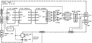
To steal the I2S signals just before they reach the PCM1716s, there are three resistors - R304, R305 and R306, next to square chip IC301, you could lift those resistors and solder wires on there.
Attachments

Last edited:
Usually paralleling DAC chip outputs will lower random noise level, 2 outputs 3 dB lower, 4 6 dB.
Does that only apply to paralleling the outputs of separate DAC chips, or also to paralleling the outputs of a single DAC chip?
I noticed that JVC produced DAC chips that had 8 outputs and wondered why, as they were summing those 8 outputs into a stereo pair.
Attachments
@jimk04,
What do you mean exactly by "it doesn't read" ? All is turning but the beaming doesn't lock and the head is moving trying to do so ?
Have you seen little resistor trimmer behind or near the laser head ? Sometimes it drifts and you can correct it by careful adjustment around the former marking you made with a pencil, worth to try if you see one.
Ian. Just been studying the manual today actually and yes I identified that IC301. But just to confirm this would be to inject an i2s signal into the dacs....not pinch the signal out. However if I do use a CD rom drive I doubt I'll be using an i2s anyway as they generally put out spdif. Unless I try my AK4118 spdif to 12s output board....but I will probably implement that into my Miro AD1862
Diyiiggy, thanks for the advice. I forget what it did exactly now. I soon get fed up with drive mechanisms not reading, hence my interest in using CD rom drives and they seem cheap, reliable and in plentiful supply.
Got mt CD rom drive fired up tonight just as test. The IR function works well with my Marantz remote. Only thing being the drive is noisy. See how it is when its in a chassis and isolated a bit.
Last edited:
Hi Jim, as far as I can see, you would inject the I2S at the same point, I can't see anywhere closer to the DACs than those resistors next to IC301.
Good guess. More specifically they are "source series RF transmission line terminators," that have selected to slightly over-dampen the line and reduce rise time a little. They help prevent ringing on the line from RF wave propagation reflections at impedance discontinuities. Reduced rise time is a trade off that helps reduce high frequency harmonics of clock pulses, which are the frequencies most likely to affect adjacent circuitry by way of stray coupling. Google 'time domain reflectometry' for more explanation about transmission lines and reflections.
Last edited:
Wow.... you lost me at the 2nd sentence.!
No honestly I appreciate the in depth answer. It all sinks in slowly.!
No honestly I appreciate the in depth answer. It all sinks in slowly.!
Does that only apply to paralleling the outputs of separate DAC chips, or also to paralleling the outputs of a single DAC chip?
I noticed that JVC produced DAC chips that had 8 outputs and wondered why, as they were summing those 8 outputs into a stereo pair.
This apply also to paralleling outputs of single DAC chip, but only for random noise, not to correlated quantization or dither noise. Also paralleling can fix little bit linearity error on LSB end but also if linearity error is random to + and - side between paralleled outputs. Lowest noise stereo DAC-s had inside 8 channel ESS Sabre chip where channels are paralleled.
If I think little about this paralleling, technically must be possible also to modify dither/noise shaping and quantization noise in way that they will be at least pseudo random between channels and then is also possible to lower partially this noisees with paralleling outputs.
- Home
- Source & Line
- Digital Line Level
- CD player upgrade project