If I understand what you said properly, I think my current implementation is already exactly what you described. On top of that, I moved the HQG (Star Ground) on the AMP board right at the edge of the small copper ground plane for the local decoupling of the OPS at which point the Speakers return connects to. This is the way I tried to create a low impedance ground for the OPS.
yes the star ground will have a minimum 3 pairs of caps covering ESR over the full range of frequencies, from lowest bass beyond the amps unity gain bandwidth.
say ~2,200 uF , 220 uF ,and 0.1 uF. (This is fairly easy to simulate on SPICE ) Depending on your woofer and box you can experiment with the largest cap. and added series decoupling if any , from the main bulk reservoirs. Testing with square waves may give further insight to effectiveness at HF decoupling , general stability and VAS goals.
Last edited:
I also don't understand, why people are worried about resonances with frequencies, where the NFB is not working.The concern of plane resonances is mostly theoretical, at least for audio: for example, here is an actual measurement of a 134x123mm plane, between top and bottom layers.
Material is standard 1.5mm FR4, and the plane is center-fed.
Vertical scale is in ohm.
λ/2 resonances only begin to appear above 1GHz, and they aren't very violent: because the distances from the center to the edges aren't uniform, the resonances are distributed, and somewhat compensate one another.
To get a single neat and strong resonance, one would need a center-fed circular plane, but that is not a very realistic situation.
Here, the maximum of impedance is less than 25Ω, and that's at 1.2GHz.
If bypass caps were added, the frequencies would be lowered, but so would the impedance levels
The "diminishing point" is not a point; that is the point! As you add more capacitance you get less and less improvement. Eventually you could get problems as extra capacitance needs extra wiring and ground connections etc.HiFiNutNut said:So what is the "diminishing point" for adding more capacitance???
I took out (bypassed) the last LR today from CLRC to C. It sounds overall better. But the background seems to be slightly less black comparing to before. More listening is required to confirm it.
you have omitted the r for rC or rCLRC
That little r creates a low pass filter and it's that filter that helps smooth the ripple, by attenuating the higher frequencies.
That little r creates a low pass filter and it's that filter that helps smooth the ripple, by attenuating the higher frequencies.
The concern of plane resonances is mostly theoretical, at least for audio: for example, here is an actual measurement of a 134x123mm plane, between top and bottom layers.
Material is standard 1.5mm FR4, and the plane is center-fed.
Vertical scale is in ohm.
λ/2 resonances only begin to appear above 1GHz, and they aren't very violent: because the distances from the center to the edges aren't uniform, the resonances are distributed, and somewhat compensate one another.
To get a single neat and strong resonance, one would need a center-fed circular plane, but that is not a very realistic situation.
Here, the maximum of impedance is less than 25Ω, and that's at 1.2GHz.
If bypass caps were added, the frequencies would be lowered, but so would the impedance levels
This is very interesting - I never thought of it as a waveguide before. But if we take the two dimensions and think of it as a 1/2 wave waveguide as edges of board are zero boundary conditions - I get the following.
Speed of light is about 300mm/nanosecond.
F=(300mm/nanosecond)/(2*123mm)=1.22GHz
F=(300mm/nanosecond)/(2*134mm)=1.12GHz
Do those two frequencies correspond to the measured peaks above?
We have similar considerations when making speaker baffles. Avoid round baffles as they cause large diffraction resonances. Rectangular with an offset driver is best. Or even better is a trapezoid.
No, not exactly, because two factors are missing: the speed of light in the FR4 is dependent on the dielectric constant: v=c/√ε, in this case ε≈4.7 thus the correction factor amounts to a little more than 2, but you didn't take into account the fact that the wave only has to travel half the distance of one side to the edge before being reflected, and that factor is exactly 2, and almost compensates for the celerity error, which means your figures end up almost exact for the λ/2 resonances.Speed of light is about 300mm/nanosecond.
F=(300mm/nanosecond)/(2*123mm)=1.22GHz
F=(300mm/nanosecond)/(2*134mm)=1.12GHz
Do those two frequencies correspond to the measured peaks above?
The first λ/4 resonance occurs just under 600MHz, and it isn't very visible because of the linear vertical scale, but it is a few tens of milliohm.
It is possible to make a simplified simulation in spice, but for audio, even such a crude approximation is already massive overkill....
Solutions - Simulating Power Planes with LTspice IV
Inductor for audio frequencies is simply a resistor. On it drops the voltage harmonics of the audio signal current on the power rails. These he makes a mud the supply.
Hard to agree with this. An inductor is NOT simply a resistor.
As far as the resulting "sound" heard in a given application/amp, I'd say that it depends entirely upon the specific situation and can not be predicted.
It would be a good idea to fork over some $$ for a decent soundcard+freeware or a QA400 and see if you can detect changes in your harmonics and noise floor. That would be a good plan.
Unrelated to the above quote - PSRR is often thought of as "FREE" in an amp design that happens to have high PSRR.
In my view, and I do not know if it has ever been stated elsewhere or not: "ain't no free". That is, in order to cancel power supply artifacts, the AMP has to do "work". Said amp is not free of distortion when amplifying anything, and it has to cancel those PS artifacts actively. It's going to be imperfect and perhaps even contribute to the spectra of distortion... especially under dynamic load conditions where the noise and ripple of the PS gets worse as power increases.
So imho, it is always a very good idea to get the noise & ripple artifacts to a minimum (amplitude and "shape"), especially under load, getting that as low as is possible. And, to make whatever is there as non nasty looking as it can be.
Hard to agree with this. An inductor is NOT simply a resistor.
Tip cascades, never letting in interference from the power suply in the signal is a CB and CC. Cascade CE, especially with Miller compensation, - the open road for interference from power supply.T117 Inductor for audio frequencies (and up to 20 harmonics of the higher frequency sound range - 20kHz) is simply a resistor.
Should be protected from interference in the first place VAS and sensitive to interference input stages with a weak signal level. Output stage protection from interference is not needed due to CC in it, large signal levels and large gajn of the preceding stage.
I wrote above that the split rail power supply the VAS and OS - good idea.
Last edited:
Yeah, well, if that were true, then we'd use resistors and capacitors for speaker crossovers, not inductors, capacitors and sometimes resistors, eh? (these being "audio frequencies")
Dunno what sort of inductors you use, but they are not simply resistive. Can't see what basis there is for your statement.
Dunno what sort of inductors you use, but they are not simply resistive. Can't see what basis there is for your statement.
you have omitted the r for rC or rCLRC
That little r creates a low pass filter and it's that filter that helps smooth the ripple, by attenuating the higher frequencies.
What is that r?
I can see that in each of the twice mains cycles, when the diodes are turned on, there is some impedance from the mains impedance and transformer impedance. But when the diodes are turned off, the source is like an open circuit. So what is this small r stands for?
I'm interested in knowing that. I briefly measured the rails yesterday when I got rid of the last LR and found the waveforms were better than I expected - they were not as sharp (triangle) on the edges which means that there is some r somewhere. I didn't think the PCB or wire resistance is large enough to create that effect.
The difference - in the inductance of these coils: number of turns, wire diameter, winding diameter, winding height, size and material of the core. As we say: if anything is unclear, read the manual. 😉Yeah, well, if that were true, then we'd use resistors and capacitors for speaker crossovers, not inductors, capacitors and sometimes resistors, eh? (these being "audio frequencies")
Dunno what sort of inductors you use, but they are not simply resistive. Can't see what basis there is for your statement.
You can also simulate the work of the coil, its effect on the impedance and resonances in your power supply. I usually do so.
I have given the amp more listening after changing it from CLRC to C. There are things better and worse. The worse is the "Z..." much stronger in female voices.
Be careful using higher inductance in DC supplies. Under transient conditions (turning it off / on ) they may pack a wallop. They also need to be deQ'd or you could easily get gain in the bargain.
you have omitted the r for rC or rCLRC
That little r creates a low pass filter and it's that filter that helps smooth the ripple, by attenuating the higher frequencies.
Andrew, also what is the approximate value of your r?
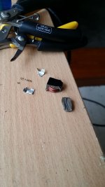
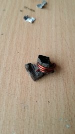
To satisfy whose who are curious about the 1uF 32A 50A(sat) DCR=2.1mR SRF=45MHz SMD inductors, I have sacrificed one for you to look at the inside of it.
It has 3 turns. The wire diameter is about 0.8mm to 1mm. The whole inductor is wrapped with iron core material and that is how it is also SHIELDED. In other words, the core materials and the shield is one piece. I have measured it with a LCR meter and it showed 1uH.
It looks like it should work as the data sheet indicates.
Attachments
the sum of all the resistances in the secondary charging circuit.Andrew, also what is the approximate value of your r?
Could be 0r1 to 10r depending on the current capacity of the components.
It is possible that the primary circuit adds to this via the turns ratio.
The difference - in the inductance of these coils: number of turns, wire diameter, winding diameter, winding height, size and material of the core. As we say: if anything is unclear, read the manual. 😉
You can also simulate the work of the coil, its effect on the impedance and resonances in your power supply. I usually do so.
An inductor may have a resistive component (usually does) but that does not make IT into a "resistor", your statement said that they were the same thing, or equivalent.
Perhaps it is a language/translation issue? I do not think you meant to say that inductors are the same as resistors??
Which "manual" do you recommend??
To satisfy whose who are curious about the 1uF 32A 50A(sat) DCR=2.1mR SRF=45MHz SMD inductors, I have sacrificed one for you to look at the inside of it.
It has 3 turns. The wire diameter is about 0.8mm to 1mm. The whole inductor is wrapped with iron core material and that is how it is also SHIELDED. In other words, the core materials and the shield is one piece. I have measured it with a LCR meter and it showed 1uH.
It looks like it should work as the data sheet indicates.
These inductors have very tiny ferrite cores - they're undoubtedly designed for pulse operation. Unless some new core material has been invented, they're not going to be happy with very much current at DC, they'll "revert" back into being slightly inductive wire once the core saturates.
Note the test conditions are at 100kHz??
Application: DC-DC converters??
Anyone have information to the contrary?
Last edited:
to be useful in a linear supply, you'd want an inductor that was rated at the power level required (amps x volts) for the peak draw of the amp, and either with a core that looks like an EI core transformer, OR for lower mH values, like an inductor for a speaker crossover. The speaker xover inductor is likely feasible for moderate values in amps of approx <100watts, becoming easier to do at lower power levels.
Also, ur looking on that spec sheet at values that in the uH, very small and will work only at very very high freqs, for small values like that you're better off with an air core and of some appropriate number of turns... with the air core you will not have saturation effects from a core.
Anyone paying attention here??
Last edited:
- Status
- Not open for further replies.
- Home
- Amplifiers
- Solid State
- Capacitor Array on Power and Ground planes – How to Avoid Resonance?