There are special core materials made of nano crystals that don't saturate as easily.
Ferrite Based Inductors : CWS Coil Winding Specialist, manufacturer of transformers, inductors, coils and chokes
Ferrite Based Inductors : CWS Coil Winding Specialist, manufacturer of transformers, inductors, coils and chokes
So you're saying that that inductor may meet the datasheet saturation curve at DC, but once there is voltage across the inductor and not just current going through it, it may saturate much easier than expected?
Also, it seems pretty clear to me that T117 is saying that at audio frequencies, the inductance of the inductor is insignificant compared to it's resistance - hence, at audio frequencies it is effectively a resistor.
Also, it seems pretty clear to me that T117 is saying that at audio frequencies, the inductance of the inductor is insignificant compared to it's resistance - hence, at audio frequencies it is effectively a resistor.
I wanted to say exactly that. You understood me correctly.An inductor may have a resistive component (usually does) but that does not make IT into a "resistor", your statement said that they were the same thing, or equivalent.
Perhaps it is a language/translation issue? I do not think you meant to say that inductors are the same as resistors??
Capacitors and inductors affect the impedance only when their reactance becomes comparable in magnitude to active, ohmic resistance of the circuit. Here the inductance of the inductor is so small that it begins to affect very high frequencies, much higher frequencies of the audio range and even above the 20th harmonic of 20 kHz. Up to these frequencies works only the resistance of the inductor.
So I call a cat a cat: to these frequencies, the inductor is not an inductor, but simply a resistor.
Actually, I think we don't need to worry about the resonances, whose frequency is higher than the frequency band of the work of the NFB. Usually this strip seldom exceeds 3 MHz, and in exceptional cases up to 7 MHz.
We need rails with so low an impedance as possible. The inductor, its resistance increases the impedance of the rail. Therefore, we do not need inductors in the power rails.Which "manual" do you recommend??
Yes, T117, clear now.
But the spec sheet shows the test voltage = 1v.
And again the spec is for PULSED operation @ 100kHz.
This would be a fine inductor for decoupling the PS to an opamp, imo, and then at
some RF freq...
The impedance of the rails??
That's going to also be a function of how much current is drawn on peaks, and the relationship between the available energy available from the source closest to the output devices WRT the time it takes to restore the charge given the max rate of discharge.
So, there is nothing about putting an inductor between sections of a PS filter that in and of itself is going to have a negative effect on the "impedance of the rail". In some cases there is substantial benefit to be had by including an appropriate inductance.
You could make a case for the filter to be a "choke input" type, and one could even in some instances utilize the "inductive kick" available by putting an inductor at the end of the filter - although this is not a common design practice.
There would also be some difference in the design goals for the PS between a Class A amp and a Class AB amp...
But assuming ample current is available, and the voltage drop under full load is minimal, there is usually a sonic benefit to the reduction of ripple, regardless of how good the PSRR. At least that's been my experience. Even so, there are situations where what one thinks ought to be best and what one hears as "best sounding" are at odds.
------
Back to what I said, for this application, in a high power (relatively) linear supply , to get an inductor to work properly at
DC and many Amps, where you want it to work in the MHz, use an air core. That's just a few/several turns of #10 or #12 wire, assuming you want a low DCR. Now whether or not this makes sense or will help in the design is another matter.
(look at the output "Zobel" that is used on many power amps, as a simple example)
_-_-
Last edited:
There are special core materials made of nano crystals that don't saturate as easily.
Ferrite Based Inductors : CWS Coil Winding Specialist, manufacturer of transformers, inductors, coils and chokes
Where in that datasheet does it say nano crystals?
What is a nano crystal, and I know about lens coatings.
Nanocrystalline magnetic cores:
http://www.hilltech.com/pdf/hl-fm10-cFinemetIntro.pdf
Although there is no mention of nanocrystalline stuff in the Bourns datasheet.
Can someone say what kind of saturation/failure you are expecting from these inductors?
http://www.hilltech.com/pdf/hl-fm10-cFinemetIntro.pdf
Although there is no mention of nanocrystalline stuff in the Bourns datasheet.
Can someone say what kind of saturation/failure you are expecting from these inductors?
The kind where it no longer is effective as an inductor?
Dunno... maybe you can saturate the heck out of these, run them at several amps of
DC @ some voltages typical of power amps and they are rock solid. What do you think?
Perhaps they don't saturate in these conditions. It would be useful to drop some significant DC through them at a reasonable current (via a load resistor) and then feed some HF via a cap and look at the load side and compare with and without DC. I'm willing to be amazed.
Who's game? 😀
These inductors have very tiny ferrite cores - they're undoubtedly designed for pulse operation. Unless some new core material has been invented, they're not going to be happy with very much current at DC, they'll "revert" back into being slightly inductive wire once the core saturates.
The important thing is that when saturated if it reduces the inductance only without generating its own noise then there is no problem. They use iron material which doesn't generate noise? I read somewhere and somebody said that with normal ferrite core when saturated it generates its own noise.
...for small values like that you're better off with an air core and of some appropriate number of turns... with the air core you will not have saturation effects from a core.
Anyone paying attention here??
I initially thought of air core. Somebody warned me that air core inductor with rectifying currents of a power amp would spray RF everywhere.
That was why I chose an iron core shielded inductor.
Yes, T117, clear now.
But the spec sheet shows the test voltage = 1v.
And again the spec is for PULSED operation @ 100kHz.
This would be a fine inductor for decoupling the PS to an opamp, imo, and then at
some RF freq...
The impedance of the rails??
That's going to also be a function of how much current is drawn on peaks, and the relationship between the available energy available from the source closest to the output devices WRT the time it takes to restore the charge given the max rate of discharge.
So, there is nothing about putting an inductor between sections of a PS filter that in and of itself is going to have a negative effect on the "impedance of the rail". In some cases there is substantial benefit to be had by including an appropriate inductance.
You could make a case for the filter to be a "choke input" type, and one could even in some instances utilize the "inductive kick" available by putting an inductor at the end of the filter - although this is not a common design practice.
There would also be some difference in the design goals for the PS between a Class A amp and a Class AB amp...
But assuming ample current is available, and the voltage drop under full load is minimal, there is usually a sonic benefit to the reduction of ripple, regardless of how good the PSRR. At least that's been my experience. Even so, there are situations where what one thinks ought to be best and what one hears as "best sounding" are at odds.
------
Back to what I said, for this application, in a high power (relatively) linear supply , to get an inductor to work properly at
DC and many Amps, where you want it to work in the MHz, use an air core. That's just a few/several turns of #10 or #12 wire, assuming you want a low DCR. Now whether or not this makes sense or will help in the design is another matter.
(look at the output "Zobel" that is used on many power amps, as a simple example)
_-_-
Excellent advice. Thanks.
What do you think of this?
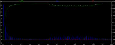
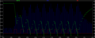
I have simulated the power amp PSU with LTSpice.
Green: Rail Voltage
Blue: Current going through rectifier diode
Red: 5A Pulse
The simulation starts from amplifier turning on to 1.2 seconds after turn on. The second image is a "zoom in" of the first. The 5A pulse simulates possibly the worst case scenario when playing music. The intent is to see the power supply ripples under such an extreme condition. It comes in after the rail is settled at 0.5 second and stops after 1 second so that I can observe recovery.
Let me know if the PSU is adequate or not for an average class AB amp. The voltage drop was over 3V. Would you add more capacitance?
Attachments
Last edited:
Correction. In the above I created a 7A pulse, not 5A, to simulate the load.
Other conditions:
Amplifier idle current was assumed 300mA. It was half wave rectification, which means in real life with full wave rectification the diode current would be halved, and I cheated with 100Hz (to simulate full wave rectification) instead of 50Hz. The small r (Andrew's) before the C was assumed 0.1R (probably too low, which means recovery would be worse).
Last edited:
Assuming you want the behavior of the inductor, then you'd have to test an actual inductor, unless the simulation has the means to fully take into account the behavior of the core material itself.
You want a static load, and to inject HF AC, look at the load side to see the result.
--------------
I guess you've moved past that issue to the PS as a whole now?
Regarding the PS of the actual amp as whole?
I guess you'd want to simulate a music signal. There aren't many high rise time squarewaves or pulses generated by the typical sources for music playback. Maybe something like a gated HF sinewave would suffice? But again, I'd look at the actual amp, since in the end you're going to have to do that anyhow.
Looking at your simulation - suggest using full wave in the simulation since you are concerned about the waveform shape not just the absolute values.
Maybe do an FFT on the diode's current waveform (but best to do that with a full wave per the actual supply) and see what that looks like? Might be interesting.
Also, some people like "soft recovery" diodes.
And, then too there are "snubbers" which may be of some benefit.
I don't quite understand why adding more capacitance improved the sound in my last 2 experiments. From simulations, it looks like the capacitance already smooths out all sharp edges. The voltage goes up and down slowly comparing to audio frequencies. I would expect that provided there is no clipping the voltage variations don't affect the sound but in reality they do. Why?
Just for yuks, why not try the simulation with a BIG inductor between the last two sections of filter caps? Wonder what the voltage waveform will end up looking like?
Not to mention the current charging waveform(s).
Big, as in >50mH and as much as 1Hy (it's a simulation, so the parts are cheap!) 😀
_-_-
Not to mention the current charging waveform(s).
Big, as in >50mH and as much as 1Hy (it's a simulation, so the parts are cheap!) 😀
_-_-
I don't quite understand why adding more capacitance improved the sound in my last 2 experiments. From simulations, it looks like the capacitance already smooths out all sharp edges. The voltage goes up and down slowly comparing to audio frequencies. I would expect that provided there is no clipping the voltage variations don't affect the sound but in reality they do. Why?
No actual idea that is solid, some conjecture.
1) ur PSRR is not really as high as it is on paper
2) more or less capacitance changes the charging current quite a bit
3) there may be more noise from the rectifiers getting through than you think (more capacitance = more charging current = more noise)
4) the transformer may be straining (it's having a hard time with delivering peak current to re-charge the caps
5) look at current, not voltage when deciding what goes up or down
6) some other factor
7) it's placebo effect
8) get a measurement tool and see if you can find it with a straight FFT or a two tone IM measurement - find a difference in the higher harmonics
9) look at the shape of a 1kHz square wave using the actual amp and see if you can find ANY difference in the leading edge or ringing (that's something that can be an indicator)
Remember an amplifier is only a device that controls the power that comes via the power supply, which is then sent to the speaker.
Music signals can't be worse than those pulses I created. So with real music the rail voltage should look much better than my simulation. Apparently adding more capacitance does not change the rail voltage forms at all but only reduce the ripple amplitude. So why it affects the sound so much?
Yes you are right that I have now solved the original problem I had. Thanks a million for you guys helping me to achieve that. My amp now sounds very good. I am asking these questions just to learn more.
Yes you are right that I have now solved the original problem I had. Thanks a million for you guys helping me to achieve that. My amp now sounds very good. I am asking these questions just to learn more.
We solder the BIG INDUCTOR and immediately leads to the deterioration of the filter by approximately 8 dB. We need this?Just for yuks, why not try the simulation with a BIG inductor between the last two sections of filter caps? Wonder what the voltage waveform will end up looking like?
Not to mention the current charging waveform(s).
Big, as in >50mH and as much as 1Hy (it's a simulation, so the parts are cheap!) 😀
_-_-
We have not received the order for a diversion.
Attachments
Last edited:
We solder the BIG INDUCTOR and immediately leads to the deterioration of the filter by approximately 8 dB. We need this?
We have not received the order for a diversion.
Try taking out all the elements you have there, and replace them with a simple C-L-C "pi' filter and compare that to the C-R-C equivalent??
Impedance is not the sole measurement of quality.
Best to have a low output impedance for your amp, if ur into low Z stuff.
Also you have no load present in ur simulation.
Are you looking ONLY at the results out at some MHz??
I'm not sure what we're seeing, the one after the choke seems to have everything much lower in level...
- Status
- Not open for further replies.
- Home
- Amplifiers
- Solid State
- Capacitor Array on Power and Ground planes – How to Avoid Resonance?