I don't know what it means: 'low Q' and 'highly resonant' are direct opposites so nothing can be both at the same time!HiFiNutNut said:I can now understand the planes make a lousy low Q RF cap. But why is it highly resonate? What does it mean?
Yes. The extra R may be unnecessary, but they will do little harm.What about line level PSU out of a regulator? I have implemented heavy CLRCLRC before the LM317/337 regulators. My understanding was that the regulators provide low impedance output regardless of the regulator input impedance, provided that there is some reasonable size of C in front of the regulator. In other words, while the CLRCLRC for my unregulated power amp degraded the sound, the CLRCLRC (with much higher R values of 10R instead of 0.1R) for my line level regulator poses no problem. Am I right?
What about line level PSU out of a regulator? I have implemented heavy CLRCLRC before the LM317/337 regulators. My understanding was that the regulators provide low impedance output regardless of the regulator input impedance, provided that there is some reasonable size of C in front of the regulator. In other words, while the CLRCLRC for my unregulated power amp degraded the sound, the CLRCLRC (with much higher R values of 10R instead of 0.1R) for my line level regulator poses no problem. Am I right?
From the big R there is no harm, if there are no large currents, create large voltage drop from the signal of harmonics, or from charging currents through the rectifier, and if this damage removes the regulator. In all other cases, we consider R and L as parameters to be elimination.Yes. The extra R may be unnecessary, but they will do little harm.
I have uploaded material that i googled few years back, if you have seen it, then let it be.
From my experience, i would go vise versa, more capacitance before the inductor and a lot less after, that way you will provide some damping of some kind. And then some smaller electros near output stage, 220uF.
I still can't figure it out, what inductor's do to the sonic's, possibility is that they mask the sound a little bit..., on the oscilloscope they tend to flatten("mask") the trace even further.
I have removed inductors from the circuit CLCLC after few months of listening and replaced with CRCRC (R=50mR)and reported improved sonic's, but softer bass in NAIM like circuits.
From EMI, you are allready protected, your transformer and diode bridges are doing they job...
Wiring the amplifier and ground are the most important aspects Here comes you EMI too.
Use resistors as CRCRC only if you want to improve higher frequency bass response, some systems will benefit heavily, some will introduce booming sound and messed up damping factor, speaker dependent also.
LM317 and 337 sounds good with CRCRC, 470uF being last C, R= 470mR, first C 2.2mF.
Why don't just build simple PSU with out R's and L's, wire it properly (naim like wiring) and have a listen ? I have feeling that more complex PSU gets you very cool QUIET amplifier, but **** sounding. I would rather listen to the opposite.
Don't take my post seriously, it is just one guy opinion from experience.
But lately, i finished second, this time original NAIM circuit... i got some 50 or 100hz HUM in speaker... quiet from distance, hear-able if put ear to speaker. But the sound is suprisingly awsome.
From my experience, i would go vise versa, more capacitance before the inductor and a lot less after, that way you will provide some damping of some kind. And then some smaller electros near output stage, 220uF.
I still can't figure it out, what inductor's do to the sonic's, possibility is that they mask the sound a little bit..., on the oscilloscope they tend to flatten("mask") the trace even further.
I have removed inductors from the circuit CLCLC after few months of listening and replaced with CRCRC (R=50mR)and reported improved sonic's, but softer bass in NAIM like circuits.
From EMI, you are allready protected, your transformer and diode bridges are doing they job...
Wiring the amplifier and ground are the most important aspects
Here comes you EMI too.Use resistors as CRCRC only if you want to improve higher frequency bass response, some systems will benefit heavily, some will introduce booming sound and messed up damping factor, speaker dependent also.
LM317 and 337 sounds good with CRCRC, 470uF being last C, R= 470mR, first C 2.2mF.
Why don't just build simple PSU with out R's and L's, wire it properly (naim like wiring) and have a listen ? I have feeling that more complex PSU gets you very cool QUIET amplifier, but **** sounding. I would rather listen to the opposite.
Don't take my post seriously, it is just one guy opinion from experience.
But lately, i finished second, this time original NAIM circuit... i got some 50 or 100hz HUM in speaker... quiet from distance, hear-able if put ear to speaker. But the sound is suprisingly awsome.
Attachments
Last edited:
As always, too sharp resonance peak means that, the resonant contour has very small losses. Loss of contour due to the conversion of the energy contour in the heat. Energy converts to heat only one element: the resistor. Sometimes it is useful to set to the battery with big capacitors, several capacitors with 1000 uF and a high ESR value, so that their resistance to the energy of the contour is converted into heat and the resonant peak decreased.looking back and read your expert advice. I can now understand the planes make a lousy low Q RF cap. But why is it highly resonate? What does it mean?
But the elimination of resonance is not the end. Battery with high-capacity capacitors have large ESL, which limits the bandwidth of low impedance PSU. For expansion band low impedance PSU must be installed in the battery as a lot of ceramic capacitors.
So, the solution is the application together with large capacitors of several EC small capacity with a large ESR, and ceramic capacitors with high self-resonant frequency, low ESR and ESL.
looking back and read your expert advice. I can now understand the planes make a lousy low Q RF cap. But why is it highly resonate? What does it mean?
say yer building a high power RF filter, maybe a simple peaking filter at 100 Mhz
the passband will have more attenuation (low Q) than the model shows and the stopband will have other woop-te-doos (resonances) at higher frequencies. At even higher frequencies the single plate cap can turn into a cavity resonator.
Last edited:
I still can't figure it out, what inductor's do to the sonic's, possibility is that they mask the sound a little bit..., on the oscilloscope they tend to flatten("mask") the trace even further.
I have removed inductors from the circuit CLCLC after few months of listening and replaced with CRCRC (R=50mR)and reported improved sonic's, but softer bass in NAIM like circuits.
Inductor for audio frequencies is simply a resistor. On it drops the voltage harmonics of the audio signal current on the power rails. These he makes a mud the supply.
The idea is to use chokes in the power supply came from tube technology. But they demand for good performance small currents with a stable value of a few milliamps. With increasing sound component of the current of the inductance requires more, comparable in size with a power transformer, and with increasing DC component of these currents up to several amperes are required to establish an increasing gap in the magnetic system of the inductor. For transistor amplifiers this idea is ill-suited, except the installation of LC-dividers in the power supply circuit OpAmp, where the inductor replaces the resistor.
I custom built a power box out of some of the best commercial mains filters. This power box powers up all of the components in my audio system. With the mains filter box, it sounds better. I have many friends listening to it, comparing with and without it, blind and not blind, with my system or others. The conclusion has always been that the mains filters improve the sound.
It was for that reason I wanted a PSU to work to RF. But of course I did it wrong as I ignored the subsonic impedance as DF rightly pointed out. But it doesn't mean it is useless to clean up RF on the rails. LC networks can attenuate RF but the difficulty is that you must use some R to dampen the LC resonance and this R can be large enough to create even bigger problem at subsonic frequency than what it helps to reduce the RF noise.
Given that amps have higher PSRR at low frequency than high frequency I see no need to have a large L which demands a larger R.
Anyway, when I have the time I will remove the last LR and see if the small remaining R causes more problem than it solves.
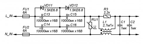
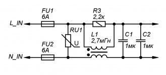
Another very good way to get rid of the power interference is to divide the power supply circuit VAS and output stages. Then VAS, susceptible to interference and low current consumption, will supply clean voltage, and the output stages are almost insensitive to interference. I have suggested this easy way, is a long tradition here with us.
Interference problems from network a little beyond the scope of discussion, but we beat them:
Interference problems from network a little beyond the scope of discussion, but we beat them:
Attachments
Last edited:
I custom built a power box out of some of the best commercial mains filters. This power box powers up all of the components in my audio system. With the mains filter box, it sounds better. I have many friends listening to it, comparing with and without it, blind and not blind, with my system or others. The conclusion has always been that the mains filters improve the sound.
But it doesn't mean it is useless to clean up RF on the rails. .
Perhaps you have a RF problem in your home or some placebo effect is happening.
Best practice is find the source of this "RF noise" OR find out where the susceptibly is worse. Look at all the entry points, and / or high gain/impedance stages. You need to do more trouble shooting at the box /system level 1st. You have somehow determined the power amp is the culprit and are now adding band-aids inside? I often see many 'young players' "fixing" a perceived problem with mods and creating real issues in other areas.
BTW often an audio amp OPS creates its own HF noise. It's basically a commutating power switch. HF decoupling at the sources of "noise" is the best solution.RF Filters on the main PS rails is stupid. full stop
Last edited:
HF decoupling at the sources of "noise" is the best solution.
I'd be interested in knowing how you decouple at the OPS.
I was trying capacitor array on power and ground planes. Others put some 0.1uF film caps close to the output devices.
I'm pretty sure once you've organized the layout and grounding, this solves 90% of the battle for lowest ripple on the rails. Decoupling caps are chosen based on esr and frequency. Cap lead spacing = LS, is directly related to freq of resonance). You must be able to visualize the current provided from decoupling caps at HF and keep this loop (source to returns ) area small. As you know, small series elements (or wires inductance in high current stages ) are force multipliers in decoupling tasks!
For the OP stage I would select (narrow LS) electros ~100-300 uF in parallel w/ small ceramic caps. For the ultimate performance, each of the 3 stages on a conventional PA gets its own dedicated supply based on its PSSR requirements & use star grounding. The problem on split rails is, currents are based on half cycles, then complexity on visualizing what's happening begins. See that's part of the problem with using large power planes, it becomes very difficult to control the returning currents! Something about the simplicity Class A and single rail supplies speaks out.
RF ingress is rarely a problem on power amps. Then it's best reduced at all the inputs and /outputs to earth ground, not the rails central point!
Last edited:
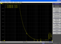
The concern of plane resonances is mostly theoretical, at least for audio: for example, here is an actual measurement of a 134x123mm plane, between top and bottom layers.
Material is standard 1.5mm FR4, and the plane is center-fed.
Vertical scale is in ohm.
λ/2 resonances only begin to appear above 1GHz, and they aren't very violent: because the distances from the center to the edges aren't uniform, the resonances are distributed, and somewhat compensate one another.
To get a single neat and strong resonance, one would need a center-fed circular plane, but that is not a very realistic situation.
Here, the maximum of impedance is less than 25Ω, and that's at 1.2GHz.
If bypass caps were added, the frequencies would be lowered, but so would the impedance levels
Attachments
The concern of plane resonances is mostly theoretical, at least for audio: for example, here is an actual measurement of a 134x123mm plane, between top and bottom layers.
Material is standard 1.5mm FR4, and the plane is center-fed.
Vertical scale is in ohm.
λ/2 resonances only begin to appear above 1GHz, and they aren't very violent: because the distances from the center to the edges aren't uniform, the resonances are distributed, and somewhat compensate one another.
To get a single neat and strong resonance, one would need a center-fed circular plane, but that is not a very realistic situation.
Here, the maximum of impedance is less than 25Ω, and that's at 1.2GHz.
If bypass caps were added, the frequencies would be lowered, but so would the impedance levels
Thanks, Elvee. That gives the best answer to the original question asked. With measurement taken what can be more convincing than that?!!!
For the OP stage I would select (narrow LS) electros ~100-300 uF in parallel w/ small ceramic caps.
When I first built this amp, I had 220uF near the output MOSFETs and I experimented paralleling it with a MKP cap of value ranging from 100pF to 0.1nF. Without the film cap, the sound appeared to be a bit dull / muddy. With the film cap, the sound appeared to be "Hard". Eventually, I had 10 x 1uF MKP (relatively high inductance) capacitor ladder and the sound was better than any of the smaller caps or without.
For the ultimate performance, each of the 3 stages on a conventional PA gets its own dedicated supply based on its PSSR requirements & use star grounding. The problem on split rails is, currents are based on half cycles, then complexity on visualizing what's happening begins. See that's part of the problem with using large power planes, it becomes very difficult to control the returning currents! Something about the simplicity Class A and single rail supplies speaks out.
The IPS and VAS of my amp are basically running on DC. I have a capacitor multiplier that has reasonably low impedance output to drive the IPS and VAS. I measured the IPS and VAS rails while I was playing music at live level and saw no ripples above 10Hz right up to my scope limit. With 2mV Div I saw basically a flat line / noise floor. The voltages go up and down slowly with power supply fluctuations but all ripples above about 10Hz were smoothed out, leaving the lines look like 1 or 2Hz waves.
That is why I was surprised that adding more capacitance to the power rails which drive the OPS only could still produce remarkable improvement in sound quality perception, as I thought the OPS naturally has high PSRR, much higher than the IPS and VAS, and rail ripple reduction was unnecessary. That was why my original PSU design had relatively high DC impedance, as I thought it shouldn't matter. Of course, I was wrong.
Last edited:
For the ultimate performance, each of the 3 stages on a conventional PA gets its own dedicated supply based on its PSSR requirements & use star grounding.
When designing the PCB ground / layout, I was struggling a bit.
What you implied is that each of the IPS, VAS and OPS stages has its own ground and each has separate connection to the star ground.
I could have done that but I have not. I thought the VAS rail takes current from the OPS rail, and the IPS rail takes current from the VAS rail (all amp schematics are drawn that way, anyway), so for proper current return, the IPS ground should connect to the VAS ground, and the VAS ground should connect to the OPS ground. i.e. the ground return reverses the current path. Therefore, I have the OPS Rail -> C Multiplier and the ground follows the same way. In any case, the IPS and OPS ground are PSU grounds including decoupling, CCS, etc., with no signal ground connection.
I wasn't sure which was better. The way I did it was the way easier for PCB track routing, therefore selected.
Last edited:
When designing the PCB ground / layout, I was struggling a bit.
What you implied is that each of the IPS, VAS and OPS stages has its own ground and each has separate connection to the star ground.
I wasn't sure which was better. The way I did it was the way easier for PCB track routing, therefore selected.
indeed
narrow high value electros w/low esr and paralleled ceramic for the OPS is difficult to implement* with low impedance grounds for esr to matter, therefore it's often most practical to do this close to last bulk cap. and use a cap multiplier for the other stages. often signal grounds @ IPS returns are separated to form only two returns to star point.* OPS is bulky / spread out, has low gain but most current demands. I recommend having separate PCBs for high power OPS and provide local bypassing to the speaker returns perhaps combining with the PS bulk filtering stage.
Last edited:
Generally speaking anything under say 7mv p-p of noise on a scope looking at a power amp out is "pretty good" and what's there is hard to discern between random noises, RF noises, radiated "hash" and who-knows-what.
Really? Thanks very much Bear. If that is the case, I should be relaxed. I recall I measured at most 4mV p-p noise at the amplifier's output.
or use a quarter wave stub in conjunction with a well placed MLC C0G.To get a single neat and strong resonance, one would need a center-fed circular plane, but that is not a very realistic situation.
yeah the whole idea of using large areas for SL caps isn't very realistic for audio esp when the "ground plane" isn't really a suitable RF ground.
The subsonic resistance of a cap charged at twice mains frequency is 1/(4 f C), where f is mains frequency and C is cap value.
DF, Thank you very much again. I am a slow learner and you have taken pain explaining to me how these things work. Your help has made my amp sound a lot better now.
Using the formula you gave, we have the following subsonic resistance in relation to the size of the reservoir cap:
10,000uF -> 0.50R
20,000uF -> 0.25R
30,000uF -> 0.17R
40,000uF -> 0.13R
50,000uF -> 0.10R
60,000uF -> 0.08R
You mentioned that one can look at 0.1R to 0.2R for subsonic impedance and I think you are probably spot on. I have changed the last cap from 12,240uF to 17,680uF to 27,680uF so if calculating only the last cap then I had subsonic frequency impedance from 0.41R to 0.28R to 0.18R. I found the sound quality improvement was dramatic.
So what is the "diminishing point" for adding more capacitance???
So far the change of more capacitance to the sound was dramatic. So I expect that it will still sound a lot better by adding more from the current value of 27,680uF. Too bad that there is limited space within the chassis.
Last edited:
indeed
narrow high value electros w/low esr and paralleled ceramic for the OPS is difficult to implement* with low impedance grounds for esr to matter, therefore it's often most practical to do this close to last bulk cap. and use a cap multiplier for the other stages. often signal grounds @ IPS returns are separated to form only two returns to star point.* OPS is bulky / spread out, has low gain but most current demands. I recommend having separate PCBs for high power OPS and provide local bypassing to the speaker returns perhaps combining with the PS bulk filtering stage.
If I understand what you said properly, I think my current implementation is already exactly what you described. On top of that, I moved the HQG (Star Ground) on the AMP board right at the edge of the small copper ground plane for the local decoupling of the OPS at which point the Speakers return connects to. This is the way I tried to create a low impedance ground for the OPS.
- Status
- Not open for further replies.
- Home
- Amplifiers
- Solid State
- Capacitor Array on Power and Ground planes – How to Avoid Resonance?