Yes it was a surprise that increasing the last C from 12240uF to 17680uF made such a big difference in perception of sound quality, from OK but boring sound to a lot more enjoyable sound.
Correct me if I am still wrong. I have learnt a lesson from this experiment and your posts. Basically, most of the time the rectifier diodes don't even turn on. Their turn on time is only a fraction of a charge cycle. So most of the time the mains impedance and transformer impedance are irrelevant. What is relevant is the capacitance seem from the load. The capacitor (band) determines the PSU impedance.
So for a CRC with C=10000uF will be worse than a single C=20000uF. But for a CRC with the last C=20000uF will be better than a single C=20000uF. The capacitance of the last C is the most important.
I still believe that some LR might be beneficial because given the large capacitance (especially when consisting of numerous small, low ESL capacitor band) some very small R and L will dramatically improve mid and high frequency filtering. Observing the rectified wave forms will see with a single C in the PSU the wave angle is very sharp but with CRC it rounds it up nicely. Translating the rectified wave forms using FTT will see substantially reduced noise in the PSU. People have been reporting that the old EI transformers with a lower bandwidth sound better than toroidal transformers with a high bandwidth. So some reduction of mains noise should be helpful.
I think I should either remove the last LR to further increase the "last" C, or simply add more capacitance to the last C.
Of course, the best is to have an amp with very high PSRR in which case a single C is sufficient. My amp is OK but not excellent in PSRR. So it is important for me to improve the PSU unless I can change the amp.
Last edited:
I have a rC(L+R)CC supply in a few of my amplifiers.
Compared to an rCC supply the output ripple is much more rounded, indicating that the HF content in the ripple is being effectively attenuated.
I typically use 50Turns to 150Turns of 0.6mm wire to form the L+R inductor. The bobbin is ~20mm diam and ~10mm cheek to cheek.
Compared to an rCC supply the output ripple is much more rounded, indicating that the HF content in the ripple is being effectively attenuated.
I typically use 50Turns to 150Turns of 0.6mm wire to form the L+R inductor. The bobbin is ~20mm diam and ~10mm cheek to cheek.
Some L can be useful, but not 1uH - far too small to do anything. Don't try to do RF filtering and audio filtering in the same filter section. My guess is that Andrew's inductor is higher value than that, so his one may give some useful audio filtering.
Don't jump to the conclusion that only the last C matters. This may be true in the audio frequency range, but not for subsonics. Remember, a Class B amp imposes a current draw on its PSU which varies with the signal envelope (assuming the last C gets rid of all audio). The PSU needs to provide low impedance at envelope frequencies as well as audio frequencies. Adding series resistance increases subsonic PSU impedance.
The subsonic resistance of a cap charged at twice mains frequency is 1/(4 f C), where f is mains frequency and C is cap value. This assumes that the DC load is such that the cap manages to more or less fully charge each mains half-cycle - which should usually be the case. With very low values of series R you can use the total C in the PSU. For higher values you need to use just the first C - the reservoir (that is why it is called the reservoir!).
it is not a "may give", it is clearly seen when one compares the ripple pics provided by the oscilloscope.Some L can be useful, but not 1uH - far too small to do anything. Don't try to do RF filtering and audio filtering in the same filter section. My guess is that Andrew's inductor is higher value than that, so his one may give some useful audio filtering.
This is where the passive band limiting filters at the input come into play.Don't jump to the conclusion that only the last C matters. This may be true in the audio frequency range, but not for subsonics. Remember, a Class B amp imposes a current draw on its PSU which varies with the signal envelope (assuming the last C gets rid of all audio). The PSU needs to provide low impedance at envelope frequencies as well as audio frequencies. Adding series resistance increases subsonic PSU impedance.
The subsonic resistance of a cap charged at twice mains frequency is 1/(4 f C), where f is mains frequency and C is cap value. This assumes that the DC load is such that the cap manages to more or less fully charge each mains half-cycle - which should usually be the case. With very low values of series R you can use the total C in the PSU. For higher values you need to use just the first C - the reservoir (that is why it is called the reservoir!).
They ensure that the out of band signals are small and when my usual advice on the relative sizing of input filters to NFB filtering effect and to PSU capacitance/filtering effect are all followed, the PSU frequency response does not interfere with the amplifier signal.
Some L can be useful, but not 1uH - far too small to do anything. Don't try to do RF filtering and audio filtering in the same filter section. My guess is that Andrew's inductor is higher value than that, so his one may give some useful audio filtering.
I can understand that we can't do both RF filtering and audio filtering in the same filter. Therefore I opted RF filtering with the 1uH. I think RF noise still affects audio somehow. Amps have excellent PSRR at lower frequencies but poor to non existent PSRR at RF so in that way RF filtering may be more important than audio noise filtering.
I thought 1uH works because the smaller value inductor has a much higher SRF. The capacitor band consists of a large number of low ESL capacitors and these capacitors are still of fairly low inductance at RF, so RF filtering should be effective. Also, small value inductor has less chance of saturating the core.
I thought higher inductance won't work for the 2 reasons: (1) it requires a higher value series resistor to damp possible LC resonance / impedance peak but we don't want higher series resistance. (2) The inductor core can get saturated and may generate noise.
Don't jump to the conclusion that only the last C matters. This may be true in the audio frequency range, but not for subsonics. Remember, a Class B amp imposes a current draw on its PSU which varies with the signal envelope (assuming the last C gets rid of all audio). The PSU needs to provide low impedance at envelope frequencies as well as audio frequencies. Adding series resistance increases subsonic PSU impedance.
The subsonic resistance of a cap charged at twice mains frequency is 1/(4 f C), where f is mains frequency and C is cap value. This assumes that the DC load is such that the cap manages to more or less fully charge each mains half-cycle - which should usually be the case. With very low values of series R you can use the total C in the PSU. For higher values you need to use just the first C - the reservoir (that is why it is called the reservoir!).
Thanks. I think I now understand what you describe.
The questions is now how much subsonic resistance is acceptable, i.e. up to what value without affecting the sound / without increasing distortions to an extent to be audible.
I have a rC(L+R)CC supply in a few of my amplifiers.
Compared to an rCC supply the output ripple is much more rounded, indicating that the HF content in the ripple is being effectively attenuated.
I typically use 50Turns to 150Turns of 0.6mm wire to form the L+R inductor. The bobbin is ~20mm diam and ~10mm cheek to cheek.
What R values do you have on your PSUs? And what CC value?
Do you subjectively found the sound to be better with a rC(L+R)CC than rC only?
I guess that either you found that there is no saturation of the inductor core, or the iron core you use get saturated in a nice way so that it only loses inductance but doesn't generate noise of its own?
Good.HiFiNutNit said:I can understand that we can't do both RF filtering and audio filtering in the same filter.
So why are you attempting what you say you know won't work? You need to be aware that a component is not a filter; a sub-circuit is a filter. In this case it would be the 1uH inductor and the following capacitor. Electrolytics don't have low impedance for RF, so the RF filtering will be almost nonexistent. The 1uH are doing virtually nothing.Therefore I opted RF filtering with the 1uH.
1uH will work as an RF filter in conjunction with a suitable capacitor. A big electrolytic is not a suitable capacitor. For a power amp DC supply you need to think in terms of ohms. 1uH will have an impedance in the ohms range at around 160kHz. You then want a capacitor with a similar impedance - about 1uF. This will filter RF from around 160kHz upwards. To deal with the frequency decade below, you need 10uH and 10uF. You may also need 100nH and 100nF to deal with higher frequencies. Any RF filter is only effective over a limited frequency range; beyond this either component reactances become unsuitable or component parasitics change things. A big electrolytic may have low inductance, yet still present a rising resistive impedance for RF.I thought 1uH works because the smaller value inductor has a much higher SRF. The capacitor band consists of a large number of low ESL capacitors and these capacitors are still of fairly low inductance at RF, so RF filtering should be effective.
There are other ways to damp resonance, such as a CR snubber in parallel with the capacitor. Core saturation is unlikely, unless unsuitable inductors are used.I thought higher inductance won't work for the 2 reasons: (1) it requires a higher value series resistor to damp possible LC resonance / impedance peak but we don't want higher series resistance. (2) The inductor core can get saturated and may generate noise.
A starting point would be that the PSU impedance should be signficantly smaller than the speaker impedance at all frequencies from audio down to DC. Maybe aim for 0.1R to 0.2R, but recognise that the smaller the better - provided that this does not cause you to get something else wrong.The questions is now how much subsonic resistance is acceptable, i.e. up to what value without affecting the sound / without increasing distortions to an extent to be audible.
The basic issue is that by concentrating on RF filtering (and getting that wrong) you have made subsonic behaviour much worse. Concentrating on something relatively unimportant while ignoring something which matters is a classic newbie mistake; we have all done it. The classic audio PSU was simply a big cap; you will note that the closer you get to this the better you perceive the sound to be.
Thanks. I am planning this weekend to try both out - (1) by adding one 10,000uF cap to the last CLRC; and (2) Short the last LR to make it a single C.
I will report back.
I will report back.
the resistance of ~10m of 0.6mm diam copper, 20mF for an 8ohms speaker.What R values do you have on your PSUs? And what CC value?
Can't hear any differenceDo you subjectively found the sound to be better with a rC(L+R)CC than rC only?
What iron? It's air cored, 50 to 150 turns on a 20mm bobbin.I guess that either you found that there is no saturation of the inductor core, or the iron core you use get saturated in a nice way so that it only loses inductance but doesn't generate noise of its own?
the resistance of ~10m of 0.6mm diam copper, 20mF for an 8ohms speaker.Can't hear any differenceWhat iron? It's air cored, 50 to 150 turns on a 20mm bobbin.
So it is very much like an air coil inductor made for loudspeaker crossover. With higher value inductor (than mine) would capacitance starts to talk effect and degrades high frequency performance? Of course everyone seems to not have worries about RF so I may learn to think of it less.
with the very low DC resistance would there be some impedance peak within the audio band?
Today I added a 10,000uF capacitor to the last C. So it is still CLRC but the last C is now approaching 30,000uF.
I brought the amp to a friend's place and compared it to a USD $5,000 150W class B amp Simaudio Moon. My amp comfortably beat the Moon. My friend also agreed.
I will give it more listening and may remove the last LR in the power supply (2+ hours work) for an experiment.
It looks like that the more capacitance in the PSU the better the sound is. That's a surprise because my PSU only drives the output MOSFETs and the rest of the rails is driven by the low output impedance capacitor multiplier.
I think that you do not filter coil, and the magnetic antenna for the emission of harmonics of the output stage efforts in the direction sensitive to interference input stages.I typically use 50Turns to 150Turns of 0.6mm wire to form the L+R inductor. The bobbin is ~20mm diam and ~10mm cheek to cheek.
In addition, the coil is a gigantic resistance, it is unnecessary and even harmful in the power supply.
These coils degrade the quality of power supply, increasing its internal resistance and increasing the ripple from the signal to its capacitors. While parallel connection of N capacitors with their ESR and ESL reduce the output impedance of the power supply: ESR/N and ESL/N.
Standard practice is to literally pave a place free from electrolytic capacitors, ceramic capacitors maximum capacitance mounted close to the connection points of the output transistors.
Last edited:
Yes, at maybe 10's of MHz. As I said, any RF filter only works over a limited range. Andrew's filter will work; yours may not.HiFiNutNut said:With higher value inductor (than mine) would capacitance starts to talk effect and degrades high frequency performance?
True up to a point. Beyond that point you are simply paying more for capacitance and the space to put it, but get little or no audible improvement.It looks like that the more capacitance in the PSU the better the sound is.
No, the coil is a small inductance, and an even smaller resistance.T117 said:In addition, the coil is a gigantic resistance, it is unnecessary and even harmful in the power supply.
It will have little effect on ripple but it certainly won't increase it; it will reduce the higher harmonics of the ripple.These coils degrade the quality of power supply, increasing its internal resistance and increasing the ripple from the signal to its capacitors.
Is it?Standard practice is to literally pave a place free from electrolytic capacitors,
I use 100x80x6mm copper bar on my psu box, 1" thickness will be overkill 🙂Btw, no one uses 1" thick copper buss bars, perhaps 1" wide? 😀
Yes it was a surprise that increasing the last C from 12240uF to 17680uF made such a big difference in perception of sound quality.......
I read this thread on each post, firstly started with HighTech discussion, some sort of simulation and xscope measurement, something fancy to me, but this thread has happy ending. Started with complicated psu and ended with simple one.
That's why I become FW lover, due to it's simplicity on psu and amplifier schematic. maybe you can also try this simple psu arrangement. CLC with big C value and L with more than 2mH, extra rC will be good.
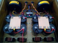
my psu box : 68mF -> 3mH 0.6Rdc -> 68mF
then it goes to amplifier chassis : with 1.2m 16awg cable -> 15mF
Attachments

Last edited:
I have a question about rectifier:
Is it better to use 4 diodes or use readymade full bridge rectifier for capacitors?
Is it better to use 4 diodes or use readymade full bridge rectifier for capacitors?
That is, it doesn't benefit either way, no way. This is evident from the model.No, the coil is a small inductance, and an even smaller resistance.
Last edited:
Hi!I use 100x80x6mm copper bar on my psu box, 1" thickness will be overkill 🙂
It's not overkill, it's a shot in the own foot. In this coil of approximately 100 turns of wire, each coil length 120 mm. 12 meters of wire with a diameter of 1 mm have a resistance of 0.2 Ohm. It is very much. Suffice it to say that a good ESR high voltage electrolytic capacitors less than 10 milliohms.
The model shows that instead of trying to smooth out the resonance capacitor, this coil creates two of their own in the region of 25 Hz and 800 kHz.
Last edited:
large area single layer caps on FR4 make lousy RF capacitors low Q and highly resonant.
looking back and read your expert advice. I can now understand the planes make a lousy low Q RF cap. But why is it highly resonate? What does it mean?
Here is a question.
I have now understood that we need low impedance PSU for subsonic frequencies for power amplifiers.
What about line level PSU out of a regulator? I have implemented heavy CLRCLRC before the LM317/337 regulators. My understanding was that the regulators provide low impedance output regardless of the regulator input impedance, provided that there is some reasonable size of C in front of the regulator. In other words, while the CLRCLRC for my unregulated power amp degraded the sound, the CLRCLRC (with much higher R values of 10R instead of 0.1R) for my line level regulator poses no problem. Am I right?
why dont you try LT1085/LT1033 to replace LM series, I used them on my dac and line level psu. I also read that there new LT device posted here, or you can try shunt regulators such as Salas shunt. your C R L value should be alligned with datasheet requirement
Last edited:
- Status
- Not open for further replies.
- Home
- Amplifiers
- Solid State
- Capacitor Array on Power and Ground planes – How to Avoid Resonance?