I think I found out today why it was I was getting confused with my odd and even crossovers (at least the electrical side anyway). The tweeter is 90 deg out of phase with the mid-bass' when both are measured raw!
That's why when I only put a cap on the tweeter and a notch filter on the midbass' I get a deep null one way and ok the other. ie to get even order behaviour I need odd order electrical on one speaker and even on the other (I think)...
the sim I'd done had 3rd order butterworth slopes (acoustically) for both drivers but flipping resulted in quite a deep null. The one I simmed that had 4th order bessel slopes (again acoustic) made no difference whether I flipped the tweeter...
So now I'm wondering, can the acoustic slope appear to be even order, but the phase is actually odd order?
Also I did some measurements today and changed over to swept sine (which worked significantly better than the previous mls measurements I'd done), and even with the cap on the tweeter I was seeing very high levels of distortion in the tweeter at around 900Hz, aprox 12%! I think I do need to up the slope on the tweeter crossover... I'd attenuated it to cut back on the sibilance, but I think that was just treating a symptom, rather than finding a cure. Probably a higher order crossover (as I can't go higher in freq) and a resonant peak filter may go a long way to fixing the sillibance, which I think will allow me to not attenuate the tweeter and end up with a better balanced sound 🙂
Tony.
Use 12 db on the tweeter and 6 db on the bass midbass.....
>>> The tradeoff is made more difficult when a rigid-cone (Kevlar, metal, ceramic, etc.) midbass driver is chosen, because the onset of breakup commonly falls in the 3~5 kHz region, right where the ear is most sensitive to distortion.
>>> As you can see, the worst possible solution is a 1st-order crossover combined with a midbass driver that has a severe breakup region (Kevlar drivers, I'm looking at you). The 1st-order crossover fails to control out-of-band excursion, so program material in the 700 Hz-2.8 kHz region results in IM distortion in the tweeter's working range, while plenty of midbass breakup in the 3~5 kHz range gets through as well. And midbass breakup sounds the same as a bad tweeter, since the distortion and resonances fall in the same frequency range.
Yup, i never had good luck with kevlar midbass and domes. I do enjoy full range drivers tho and think off axis they can sound fantastic and fatigue free.
Agree prefer Paper or poly than kevlar for the mids. 1st order xover's need just as much attn and understanding when implementing. Driver makeup is very critical and sims dont necessary tell all of the tale. I do prefer to use 12 db on the tweeter section unless it was a large ribbon or a really big cavity dome, but neither would i use more than 12 db, too much phase shift, IMO..
Lynn , what are you using for caps ...?
regards,
Last edited:
Ribbons are wonderful above 4~5 kHz, but I have reservations about the current fad of using them in audiophile minimonitors (or whatever you call a compact stand-mounted speaker that's 85~87 dB/meter efficient). The combination of a low-efficiency and breakup-prone midbass driver combined with a fashionable low-slope crossover results in a speaker that is pretty clean at low levels and carefully chosen audiophile discs, but goes to pieces at higher levels. What's missing is a ribbon-quality driver that covers the 700 Hz to 5 kHz range - those are not easy to find.
Agree, so i built my own ....🙂
First of all I'm not completely sure anybody would agree to the same sonic pattern as to be called "sibilance"
One would have to put a A/B sample for the people here to decide.
For those which have PC based sound systems, I'd recommend to simply try the following:
add a roughly 0.02ms of delay and mix with the original sound - make an EQing to roughly match tonal balance.
Then tell us about your findings with respect to "sibilance"
🙂
Michael
PS
make sure the non-delayed path goes through another plugin the of same type, set to zero
PPS
check with any decent headphone
Last edited:
Well, you'll get a sum+difference... whose spectrum corresponds to the delay time between the two signals...
What are you saying WRT "sibilance" as produced in the usual home audio system??
Also, I take "sibilance" to mean a kind of "spray" or "excess" HF associated with the human voice, perhaps a sort of "grain" but tracking certain types of vocal formants...
Not just a harshness - although that is a wider net that will include "sibilance".
_-_-bear
Also I did some measurements today and changed over to swept sine (which worked significantly better than the previous mls measurements I'd done), and even with the cap on the tweeter I was seeing very high levels of distortion in the tweeter at around 900Hz, aprox 12%! I think I do need to up the slope on the tweeter crossover... I'd attenuated it to cut back on the sibilance, but I think that was just treating a symptom, rather than finding a cure. Probably a higher order crossover (as I can't go higher in freq) and a resonant peak filter may go a long way to fixing the sillibance, which I think will allow me to not attenuate the tweeter and end up with a better balanced sound 🙂
Tony.
900 Hz!? The only HF drivers that I know of that are comfortable that low are large-format compression drivers with a decent-sized horn. I don't even like the sound of small-format compression drivers below 2 kHz.
Conventional direct-radiator 1" tweeters sound badly strained with 2 kHz crossovers - in my opinion, they are only just OK (not actually good) with a 4th-order (acoustic) crossover at 2 kHz. They are much, much better with crossovers at 3.2 kHz or above.
We hear a lot of brag from the tweeter vendors that XYZ tweeters "works great" down to some unlikely frequency, maybe 1.6 kHz or so. This kind of advertising, to be blunt, is aimed at inexperienced system designers - some of whom work for high-profile audiophile companies, judging by the gruesome sound at trade shows.
The fad for controlled directivity and pretty polar patterns has led to very poor decisions on crossover frequencies. Trying to "force" a tweeter to work below its optimum range is asking for fatiguing sound, and a speaker that changes its sonic character with level.
Rather than force drivers to fit a preconceived set of design goals, it's better to work the other way around: start with the drivers, and find out what they can and cannot do. Most domes are not suitable for use below 2.5~3.2 kHz, even with 4th-order crossovers. 5~7" midrange and midbass drivers start to get in trouble above 3.5 kHz - a few, a very few, are good to 5 kHz. This is set by the limitations of the materials used in the cone and the overall size of the cone, with cone size dominating.
I find it interesting that the Lansing Iconic used a 800 Hz 2nd-order crossover between the HF system and the 15" paper-cone woofer. That was in 1936, and it's still an appropriate crossover point for a 15" woofer today - woofer tech has not really changed all that much. Well-chosen drivers in the 5~7" range can make it to 3~5 kHz, but not much above that. Whizzer cones buy more extension at the cost of a very rough mechanical crossover and nearly total breakup in the working range of the whizzer cone. (The Altec Biflex was a better solution for a mechanical crossover.)
Work with drivers as they are, not fantasy drivers made with imaginary diaphragm materials. Yes, diamond cone drivers would be nice, or drivers made with synthetic spider silk or buckytubes. All great materials for the Skyhook to outer space, once we get costs down and can manufacture it by the ton. But for now, we have paper, various plastics, and a variety of composites - although paper itself is a composite. Aluminum and magnesium cones are rigid in their working range, but have almost no self-damping, so they store a lot of energy in the breakup region.
So if you are using a 1" direct-radiator dome tweeter, and you care about sound quality more than polar patterns, use a crossover no lower than 2.5 kHz, with 3 kHz or higher a better choice. There are a handful of 1.4" or 1.5" dome tweeters, and these are good down to 1.6~2 kHz, but you have to accept gentle rolloffs above 15 kHz and increased HF directivity. The full-size Heil/AMT's are good down to 1.6~2 kHz, and have pretty good power-handling in the upper midrange region. Not cheap though. Real aluminum-foil ribbons (not stretched film), 4 kHz on up.
If you're using a horn with a mouth size as big as a 15" driver, or preferably bigger, than you can cross at 1 kHz or lower. In short, the appropriate choice of a crossover frequency is set by boring considerations of midbass cone size (which sets the frequency of the first breakup), and the power-handling/excursion limits of the HF driver. Steer a path between these two boundaries in order for the drivers to sound their best.
P.S. Personal choice in caps? I'm using the Jupiter wax-paper-and-foil caps in the tweeter section of the Ariel crossovers.
Last edited:
Thanks Bear and Lynn, I kinda have invested too much in these (more time but also $) to start from scratch.
I was quite happy with them for a while, my biggest problem is that the midbass' didn't work out to be as flat as the original datasheet I'd seen, it has made things somewhat difficult to get a really flat response, but I'm probably trying too hard to get it really flat 😉
I think I can do something workable at 2.4Khz crossover frequency, current is supposed to be 3Khz but If I invert the tweeter the null is at around 2.2Khz which is obviously too low for a second order crossover. that current crossover is giving me around +- 2.5db 300 - 16Khz, but as I have said it has silibance issues and also sounds terrible on "dense" material.
Thanks for all of the help guys I'll soldier on 🙂
Oh and I wasn't thinking the tweeter should be able to pull off 900Hz, was just a bit shocked as to how high the distortion was at that frequency, which made me realise the importance of what you have been saying! 🙂
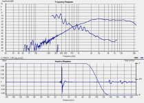
Attached is a measurement of the tweeter I did on the weekend, its a morel DMS37 by the way.
Tony.
I was quite happy with them for a while, my biggest problem is that the midbass' didn't work out to be as flat as the original datasheet I'd seen, it has made things somewhat difficult to get a really flat response, but I'm probably trying too hard to get it really flat 😉
I think I can do something workable at 2.4Khz crossover frequency, current is supposed to be 3Khz but If I invert the tweeter the null is at around 2.2Khz which is obviously too low for a second order crossover. that current crossover is giving me around +- 2.5db 300 - 16Khz, but as I have said it has silibance issues and also sounds terrible on "dense" material.
Thanks for all of the help guys I'll soldier on 🙂
Oh and I wasn't thinking the tweeter should be able to pull off 900Hz, was just a bit shocked as to how high the distortion was at that frequency, which made me realise the importance of what you have been saying! 🙂
Attached is a measurement of the tweeter I did on the weekend, its a morel DMS37 by the way.
Tony.
Attachments
Thanks for all of the help guys I'll soldier on 🙂
Tony.
Let me fix that for you "I'll solder on''. 😀
Interesting stuff. I presume the talk of slopes and points for the tweeter is to reduce (basically) low frequency content getting in.(?)
A curveball perhaps, what about active and steep slopes (Ok, not everyone likes it yada yada, that is all personal choice anyway).
Does it still apply in those cases? For sake of argument, the tweeter is better 'protected' or at least has less low FR energy when crossed 2400@60 db than 3400@12 or 18 (or whatever, have not done the maths).
Leaving aside any 'I would not touch them with a barge pole, I'll stick to caps and inductors' how does the picture change?
I'm agreement with Terry J; if you must use a brickwall filter, active is the way to go. Realizing a physical 4th-order electrical filter is no fun (capacitor tolerances start to become very narrow), and a 6th-order filter is out of the question. Also, rather than waste months of effort (your time is worth something, isn't it?), it's better to find out quickly whether the tweeter and midrange are worth keeping or not - and a brickwall active filter will quickly reveal that. If the sibilant coloration is still there with the brickwall filter, toss the drivers and start over, or live with the sibilance and make your peace with it.
Umm ... on further consideration, looking at those curves you measured, the midrange looks hopeless. Reminds me of the last time I measured Fostex drivers, or a car-radio 6x9 elliptical. The multiple resonances are beyond the scope of equalization. Maybe the ripples are really caused by diffraction, so try putting lots of felt around the mid. Is it mounted in a hole or something? They really need to be flush with the front panel to minimize diffraction.
The curves for the tweeter look OK to me. Very typical. Very minor elevated region around 3 kHz, and I would deal with that - it will cause an impression of forwardness that isn't flattering to most recordings. If you had an acceptable midrange, I'd set the crossover at 4 kHz (electrically) and let the little peak take it down to 3~3.5 kHz (acoustically). Old crossover trick - make the small peaks part of the crossover slope. The driver is trying to tell you to cross it over at 3~3.5 kHz (acoustically).
On a trial basis, I'd borrow an active crossover and a spare amplifier and do some listening. Frankly, given the atrocious measurements of the midrange, I have no idea where I would put the crossover. If you are wedded to these drivers, I'd turn the frequency knob and listen for the best overall sound. What you'll hear as you (very slowly) turn the knob will be an interesting variety of midrange colorations - you get to choose which set you like best.
Last edited:
Lynn I don't believe Tony has posted any measurements of the midrange driver. His first set of curves display the tweeter amplitude and THD level.
What mid is it you're using Tony?
What mid is it you're using Tony?
Lynn the other curve is probably the THD of the tweeter, there is a mark THD: Ok in the right corner
Chris
Sorry double post
Chris
Sorry double post
Last edited:
Good point; the distortion measurements are certainly cause for concern, in that event, since they are very high. It certainly looks like this tweeter wants a crossover between 3.2 and 4 kHz, and a fairly steep slope if possible. The suggestion to try an active crossover still applies, since that will quickly give a go/no-go quality indication about the tweeter. If that's too awkward, I would try an electrical 3rd-order highpass at 4 kHz (with an additional notch filter at tweeter Fs if necessary) and see how it sounds.
I agree with 5th element that midrange measurements (without crossover) would be illuminating. I have a feeling that this tweeter and midrange just don't work together (a very common event in the speaker biz).
I agree with 5th element that midrange measurements (without crossover) would be illuminating. I have a feeling that this tweeter and midrange just don't work together (a very common event in the speaker biz).
Last edited:
I do prefer the 4th order over the 3rd... but that is only my preference, nothing scientific about it, just the way things sounded over the years...
You can pick up a Behringer xover here in the USA for <$100 new, less used... fwiw, good for testing I guess...
You can pick up a Behringer xover here in the USA for <$100 new, less used... fwiw, good for testing I guess...
Since changing from analog to DSP in my active setup, I've come to the conclusion that steeper is better, especially in the 100 - 1k region...at least in my case and with my drivers.
Hi Guys, yes that is only the tweeter, the second curve is the THD of the tweeter!
I'll post the mid response this evening, it's on my home computer. The mid's are MW144's. They are very flat to 1Khz (nearfield) but have a prominent hump between 1 and 2 khz. a post with an old measurement of the MW144's is here --> http://www.diyaudio.com/forums/mult...m-projects-long-first-post-4.html#post2163637
Note that I think I have the measurements more sorted now but in trying to find some decent measurements in posts I've made, I discovered something a bit disturbing... my vifa m26WR-09-08's exhibit very similar response anomalies to the MW-144's This seems a bit odd considering its a 10" vs a 5" and VERY different baffle geometry.... Despite having tried many different things with my measurements (and getting pretty consistent results) perhaps there is something inherently wrong with them...
Tony.
I'm not sure that I would tar all whizzer cones with the same brush. Conical whizzer cones typically do have severe breakup modes but I would argue a really well designed curvilinear whizzer cone can be orders of magnitude better when it comes to resonances and cone breakup, to the point where it's not really an issue.Well-chosen drivers in the 5~7" range can make it to 3~5 kHz, but not much above that. Whizzer cones buy more extension at the cost of a very rough mechanical crossover and nearly total breakup in the working range of the whizzer cone. (The Altec Biflex was a better solution for a mechanical crossover.)
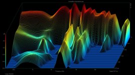
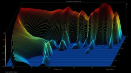
I recently measured the CSD of a couple of my 8" full range whizzer cone drivers to illustrate the point in another discussion thread over in the full range section.
The first one is the Fostex FE207E - a well known but recently discontinued driver with a 60mm conical whizzer cone. The whizzer cone resonance at 2.6Khz couldn't be more obvious - at 2ms (1.6ms after impulse stop) it's only down 8dB. In fact it takes nearly 4ms to decay 20dB when viewed on an expanded time scale. Can't be corrected in any meaningful way in the network. Sounds terrible too. 😛
The second is a Coral Flat 8 with an 80mm curvilinear whizzer cone. The fundamental whizzer cone resonance at 2.2Khz is so minor that it's decayed 20dB in 0.6ms. As it's a nice symmetrical minimum phase mechanical resonance, with the right RLC resonance compensator in the network it can actually be more or less eliminated completely, both the frequency response bump and the CSD decay tail. Most of the remaining breakup below 10Khz is actually from the outer 1/3 of the main cone (which is conical with three ribs near the outside) with very little from the whizzer. Surprisingly good showing from an 8" dual cone driver I think and it certainly sounds good, especially with the two bumps at 2Khz and 4Khz (whizzer and main cone respectively) compensated for in the network.
True, it's exceptionally hard to design a really good whizzer cone driver that is clean and relatively flat, but given the discussion about how hard it is to make a really good tweeter that performs well low in frequency, and how hard it is to design a midrange driver that goes high enough, cleanly enough, and without severe beaming and breakup, I think there is still a bit of life left in the approach, especially if modern design and measurement techniques were put to work on the problem, instead of the largely trial and error approach of a few decades ago...
What I'd like to see is a driver where the main cone was curvilinear as well as the whizzer... On the Flat 8, nearly all the flaws in the response from 2Khz-10Khz stem from onset of breakup in the main cone not the whizzer, so there is still a lot of room for improvement if the main cone were better damped and more rolled off at high frequencies. (At the moment the main cone, as measured on a de-whizzered driver extends to about 7-8Khz all by itself before rolling off at ~12dB/oct, which is too high)
Attachments
Last edited:
OK I've uploaded some more measurements (and a bit of commentary) on my build thread, as I was really starting to hijack this thread. Can be seen here 🙂 http://www.diyaudio.com/forums/mult...m-projects-long-first-post-6.html#post2615180
Tony.
Tony.
After years of using a 3rd order crossover in my current speakers (between midrange/ribbon tweeter) you've single-handedly convinced me to give a 4th order L/R a second chance, despite my reservations on the power response issue.I don't doubt acoustical 3rd-order crossovers can be done well, but I haven't had as much luck with them - managing the spatial impression is more difficult, and small ripples in the response seem to stand out more. A possible reason for the subjective impression might be the inter-driver phase angle is already at 90 degrees, and small departures from the ideal curve spread it into the danger region of 120 degrees, where unpleasant out-of-phase impressions start.
By contrast, with an inphase crossover, a small departure from the ideal curve only results in a 30-degree phase spread, which doesn't sound all that different than zero degrees. When the phase spread goes from 90 to 120 degrees, though, you can actually start to hear odd flanging and acoustic-null sounds.
I recognize them immediately as what they are, but to a listener that doesn't have a background in phase-shift networks and what they sound like, it sounds like a hard-to-pin-down coloration that doesn't have an obvious tonal center. Switching from music to wideband pink-noise gives the game away; pink-noise immediately reveals phasiness for what it is. With music the coloration comes and goes, and is very difficult to pin down. If the spectrum is sparse, you might not hear it all.
The point you make about variations in the phase spread between the two drivers (due to response anomalies in the drivers) causing the relative phase to potentially shift from 90 degrees into the "danger zone" of 120 degrees or more where cancellation begins is extremely poignant, and I hadn't really thought about it in those terms before.
As you say, in a 90 degree design you're always on a "knife edge" balance where even small additional relative phase shifts of ~30 degrees are going to cause large, asymmetrical response variations, while the same phase shift from the same driver anomalies in an in-phase design will have far less impact, and never veer towards the danger zone of >120 degrees.
Even if the phase spread doesn't quite reach 120 degrees on axis, it may reach it slightly off axis for some of the driver response anomolies, so as you move off the vertical axis progressively more isolated parts of the frequency spectrum will start to go out of phase and cancel, while neighbouring frequencies are not.
I completely agree that any cancellation between two drivers sounds bad - if the summed response has any frequency region which is lower in level than either midrange or tweeter measured alone, or reversing the polarity causes any frequency region to increase, you know you're hitting that danger zone of >= 120 degrees.
This is one reason why I've never liked the sound of a "super tweeter" with an "unfiltered" full range driver that many full range fans are fond of. They think that by not low pass filtering the full range driver that somehow the "evils" of a crossover are being avoided, but now you have a huge overlap region between the tweeter (typically 1st order high pass at ~10Khz) and the full range driver, and no matter which polarity you connect the drivers in, the phase response anomalies of the full range driver cause some frequencies to add and some to cancel.
To me this has a disjointed unfocused sound, and a properly designed crossover between the full range driver and tweeter where they actually cross over sounds far better and more focused to me. Generally the less overlap between drivers (up to a point) the more focused it sounds to me, and the more immune it is to the focus shifting when going off axis.
I think where I went wrong last time I tried a 24dB/oct L/R is that at the time (about 8 years ago) I didn't have the necessary measurement accuracy - software or microphone, to fine tune the crossover to get the right acoustic slopes with any degree of certainty.
So I had a 24dB/oct L/R electrical crossover, but in hindsight there was some droop in the order of 1-2dB in the crossover region from the midrange driver which would have prevented it from being an acoustic L/R, preventing them from summing flat, and even a 1dB depression in the presence region has serious consequences for the overall sound, making it sound lifeless and lacking in imaging and focus.
What I also found out much later is I'd mis-estimated the relative acoustic centres of the drivers by about 12mm - doesn't sound like much but it's about 45 degrees at 4Khz, so my total phase shift at the crossover frequency was only about 45 degrees instead of 90 - giving a 1-2dB boost in the presence region that almost exactly complemented the droop in the drivers response.
The 3rd order filter was sounding better not necessarily because of being 3rd order (flat power response etc) but simply because the time misalignment of the -3dB butterworth filter was correcting the response droop. 😱 Because the phase shift was only 45 degrees it was much closer to an in-phase network all along, so the power response would have still had some droop in it anyway since it was summing flat at 45 degrees instead of 90.
So what I need to do is try the 4th order L/R once again, with the tweeter correctly time aligned (12mm different z-axis from where it is now - no problem as it's in a pod on the top) and now that I can measure much more accurately I'll be careful to optimize the network to give a L/R acoustic response, which means the actual electrical low-pass filter on the midrange will probably be closer to a Butterworth.
It will be interesting to see what it sounds like, although it will be a long time before I get a chance to do any of this...
Last edited:
Lynn, I understand you also doubt that it is ok to use a 1" compressiondriver very low, and cross around 1000-1500Hz. I usually feel it sounds to "thin" using tweeters very low, but I dont have experince in using compressiondrivers in home hifi.
This setup describes very much Geddes Summit speaker, have you heard that, and how will you describe the sound of that? Does that big waveguid save the day...
Not to take over this thread, but what is going on with your Beyound the Arial project, is it on hold? Have you decided the drivers to use?
This setup describes very much Geddes Summit speaker, have you heard that, and how will you describe the sound of that? Does that big waveguid save the day...
Not to take over this thread, but what is going on with your Beyound the Arial project, is it on hold? Have you decided the drivers to use?
@ Lynn.
Why is a passive acoustic 8th order out of the question? It has been done with succes in a SB article around the year 2000, which inspired me to experiment with the concept. It is indeed neigh impossible without the proper X/O software, but provided the software has an Optimizer (Calsod Pro/LspCad Pro/SE/Leap) it is relatively easy to do. What is more: measurements agree with the simulations. Yes, group delay might be an issue, but I doubt this wil be audible. John K. has succesfully done 5th or 6th order in the past. See: Fallacy of the FR driver.
Furthermore, there is some confusion in the discussion whether it is about electric filter slopes or acoustic filter slopes. Those familiar with desiging X/O filters with the proper software, will no doubt be aware that acoustic 4th order LR often involves electric 2th or 3th order. Electric 4th order will yield a mess with a sort of 5/6th order trend.
Acoustic 1th order is very hard to achieve over at least a reasonable part of the stopband. That, in combination with insufficient tweeter protection should scare off any serious designer.
Eelco de Bode
Eelco de Bode
One of the issues with a LP of higher order is the change in Qts due to the DCR of the inductors in series... but I didn't have access to the article...
_-_-bear
_-_-bear
- Home
- Loudspeakers
- Multi-Way
- Can you have sparkling treble but without sibilance