... in the meantime, I got the schematics directly from Classé from Canada!!!!
Very friendly people in this company:
Great, isn't it? I can use the psu board and the very fine input circuit, including two paralleled 1:2 digital input trannies.
Franz
Very friendly people in this company:
This is our schematics for the DAC-1. As you know, it is a fairly old unit so I am not sure if this schematic will answer your questions. If not, please feel free to contact us and speak to one of our technicians.
Great, isn't it? I can use the psu board and the very fine input circuit, including two paralleled 1:2 digital input trannies.
Franz
CD/Kwak/XO clock 7.......
Hi Elso,
I've combined your Kwak-clock 7 design with the two-stage single supply that I found on Guido Tent's page

Is the offset adjustment implemented o.k. for the opamp this way?
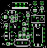
I also degined a small PCB for it, do you think it will be any good?
Greetings,
Raymond.
Hi Elso,
I've combined your Kwak-clock 7 design with the two-stage single supply that I found on Guido Tent's page
Is the offset adjustment implemented o.k. for the opamp this way?
I also degined a small PCB for it, do you think it will be any good?
Greetings,
Raymond.
Attachments
Re: CD/Kwak/XO clock 7.......
Huh, smart guy.... Offset adjustment for opamp???????
Seriously I do not believe in pre-regulators. Better improve the PI-filter. I always advice using the raw digital supply of the CDP.
The KWAK-CLOCK works better on a dual supply. Earlier versions had single supply.
BTW the power supply I am using is very similar to Cuno's Snoeren's schematic.
http://home-4.worldonline.nl/~t708955/schem/xoschema.jpg
Why want you guys to merge my schematic with Guido's? Try to improve the regulator and/or comparator. Do something original!
🙄
6h5c said:Hi Elso,
I've combined your Kwak-clock 7 design with the two-stage single supply that I found on Guido Tent's page
Is the offset adjustment implemented o.k. for the opamp this way?
I also degined a small PCB for it, do you think it will be any good?
Greetings,
Raymond.
Huh, smart guy.... Offset adjustment for opamp???????
Seriously I do not believe in pre-regulators. Better improve the PI-filter. I always advice using the raw digital supply of the CDP.
The KWAK-CLOCK works better on a dual supply. Earlier versions had single supply.
BTW the power supply I am using is very similar to Cuno's Snoeren's schematic.
http://home-4.worldonline.nl/~t708955/schem/xoschema.jpg
Why want you guys to merge my schematic with Guido's? Try to improve the regulator and/or comparator. Do something original!
🙄
Re: Re: CD/Kwak/XO clock 7.......
Hmmmm.....'you guys' ???
Sorry to step on your toes......
I'm just a DIY'er trying to put things together that are available here and there. I am under the impression that this regulator is less noisy. Sorry if I didn't use the correct offset-terminology, but I think you understand the question quite well.
But thanks for your input anyway.
Ray.
Elso Kwak said:
Huh, smart guy.... Offsetadjustment for opamp???????
Seriously I do not believe in pre regulators. Better improve the PI-filter. I always advice using the raw digital supply of the CDP.
The KWAK-CLOCK works better on a dual supply. Earlier versions had single supply.
BTW the power supply I am using is very similar to Cuno's Snoeren's schematic.
http://home-4.worldonline.nl/~t708955/schem/xoschema.jpg
Why want you guys to merge my schematic with Guido's? Try to improve the regulator and/or comparator. Do something original!
🙄
Hmmmm.....'you guys' ???
Sorry to step on your toes......
I'm just a DIY'er trying to put things together that are available here and there. I am under the impression that this regulator is less noisy. Sorry if I didn't use the correct offset-terminology, but I think you understand the question quite well.
But thanks for your input anyway.
Ray.
Re: Re: Re: CD/Kwak/XO clock 7.......
Ray, It is not an opamp but a comparator!
78XX are quite noisy as pre-regulator.😎
The J309 performs better than the J310 in my clock.
6h5c said:
Hmmmm.....'you guys' ???
Sorry to step on your toes......
I'm just a DIY'er trying to put things together that are available here and there. I am under the impression that this regulator is less noisy. Sorry if I didn't use the correct offset-terminology, but I think you understand the question quite well.
But thanks for your input anyway.
Ray.
Ray, It is not an opamp but a comparator!
78XX are quite noisy as pre-regulator.😎
The J309 performs better than the J310 in my clock.
Re: Re: Re: Re: CD/Kwak/XO clock 7.......
Oops, comparator, my mistake. See, that's where you come in. Thank goodness everybody's not as dumb as me. But that still doesn't answer my question.
Btw. I do believe in pre-regulators.
Thanks for the J310 advice.
Ray.
Elso Kwak said:
Ray, It is not an opamp but a comparator!
78XX are quite noisy as pre-regulator.😎
The J309 performs better than the J310 in my clock.
Oops, comparator, my mistake. See, that's where you come in. Thank goodness everybody's not as dumb as me. But that still doesn't answer my question.
Btw. I do believe in pre-regulators.
Thanks for the J310 advice.
Ray.
Ray,
The trimmer on the inverting input does not adjust the offset but adjusts the symmetry of the waveform.
BTW, I think that the inclusion of the BC550 transistor in Elso's regulator is not at all necessary, as current draw is ca. 12 mA for the positive and ca. 5 mA for the negative rail (I have breadboarded the clock and measured currents) and TL431 can comfortably supply those currents without any need for current boost. At least, this is how I designed mine. Just my opinion.
Evangelos
Re: Re: Re: Re: Re: CD/Kwak/XO clock 7.......
For single supply operation I suggest R6= 1k5 and the pot 2k. The pot adjusts the tripping point of the comparator, hence the duty cycle of the wave form.
I tried it with and without pre-regulator!
I hope this answers your question. I tried many, many other things!!
😎
6h5c said:
Oops, comparator, my mistake. See, that's where you come in. Thank goodness everybody's not as dumb as me. But that still doesn't answer my question.
Btw. I do believe in pre-regulators.
Thanks for the J310 advice.
Ray.
For single supply operation I suggest R6= 1k5 and the pot 2k. The pot adjusts the tripping point of the comparator, hence the duty cycle of the wave form.
I tried it with and without pre-regulator!
I hope this answers your question. I tried many, many other things!!
😎
kenev said:Ray,
The trimmer on the inverting input does not adjust the offset but adjusts the symmetry of the waveform.
BTW, I think that the inclusion of the BC550 transistor in Elso's regulator is not at all necessary, as current draw is ca. 12 mA for the positive and ca. 5 mA for the negative rail (I have breadboarded the clock and measured currents) and TL431 can comfortably supply those currents without any need for current boost. At least, this is how I designed mine. Just my opinion.
Evangelos
Hi Evangelos,
But did you compare the sound with my original schematic?
Sorry I did not visit you as I did not travel further than Kalambaka (Meteora)

Attachments
Do You think that thermal and contact voltage noise of this trimmer will not be converted by comparator into phase noise(jitter -in time domain)?
In my opinion resistance of this trimming resistor is far too big and i prefer two constant walue resistors acting as attenuator .
In my opinion resistance of this trimming resistor is far too big and i prefer two constant walue resistors acting as attenuator .
kenev said:Ray,
The trimmer on the inverting input does not adjust the offset but adjusts the symmetry of the waveform.
BTW, I think that the inclusion of the BC550 transistor in Elso's regulator is not at all necessary, as current draw is ca. 12 mA for the positive and ca. 5 mA for the negative rail (I have breadboarded the clock and measured currents) and TL431 can comfortably supply those currents without any need for current boost. At least, this is how I designed mine. Just my opinion.
Evangelos
Hi kenev,
As I use the oscillator without an output cap, since I have only a single supply available, there's about 2,5V offset present on the non-inv input. By applying the same offset to the inv. input the switching point of the comparator should move to the center of the wavform and make a 50% square wave. At least that's my idea, and it's the same as your's I think, only with a different explanation 😀
The 431 circuit uses feedback to regulate the output voltage. The divider is at the output side and provides a feedback to the 431. Any noise produced by the 431 will be present at the output because it's a closed loop, correct me if i'm wrong.
The other circuit has the divider at the input side and doesn't use feedback. The voltage at the base of the BC550 is well filtered by the divider R1/R2 and C3. Nothing more than a passive RC filter. The transistor is a simple voltage follower that provides extra current. My guess is that this transistor produces less noise than a 431 + transistor combination. But of course it may sound worse, i'm hoping to find out 😉
Greetings,
Ray.
bitrate said:Do You think that thermal and contact voltage noise of this trimmer will not be converted by comparator into phase noise(jitter -in time domain)?
In my opinion resistance of this trimming resistor is far too big and i prefer two constant walue resistors acting as attenuator .
My goodness,
Do you really thinks so?
I am am using a Cermet Vishay trimmer.
Earlier versions had no trimmer but sounded less good.....
Attachments
Re: Re: Re: Re: Re: Re: CD/Kwak/XO clock 7.......
O.k., thanks, I'll run a bit more current through that part, and I'll try it with the 431 supply also.
Ray.
Elso Kwak said:
For single supply operation I suggest R6= 1k5 and the pot 2k. The pot adjusts the tripping point of the comparator, hence the duty cycle of the wave form.
I tried it with and without pre-regulator!
I hope this answers your question. I tried many, many other things!!
😎
O.k., thanks, I'll run a bit more current through that part, and I'll try it with the 431 supply also.
Ray.
bitrate said:Do You think that thermal and contact voltage noise of this trimmer will not be converted by comparator into phase noise(jitter -in time domain)?
In my opinion resistance of this trimming resistor is far too big and i prefer two constant walue resistors acting as attenuator .
Hi Bitrate,
Won't the 100n cap take care of that?
Two fixed resistors sounds good, at least it rules that part out.
Ray.
I suggest to use low noise Vref rather than voltage divider directly from supply to adjusting duty cycle .
bitrate said:I suggest to use low noise Vref rather than voltage divider directly from supply to adjusting duty cycle .
Did you try it?
Schematic??
😕
Elso Kwak said:My goodness,
Do you really thinks so?
I am am using a Cermet Vishay trimmer.
Earlier versions had no trimmer but sounded less good.....
Thermal noise is Vendor independent so no matter if You use Vishay ,Bourns or other , value of resistor is important.
Originally posted by 6h5c
Hi Bitrate,
Won't the 100n cap take care of that?
In higher frequencies of thermal noise yes , but contact noise is 1/f noise so this cap do nothing with them.
bitrate said:
Thermal noise is Vendor independent so no matter if You use Vishay ,Bourns or other , value of resistor is important.
In higher frequencies of thermal noise yes , but contact noise is 1/f noise so this cap do nothing with them.
Hm, good point indeed. Maybe I will throw in an extra regulator and use a fixed offset voltage divider to see how that works/sounds.
How about using a LM317 with adjust pot to be able to trim the offset voltage? Does it have enough lf-rejection on it's adjust-pin?
Thanks for the tip!
Ray.
- Status
- Not open for further replies.
- Home
- Source & Line
- Digital Line Level
- Can someone send to me the Elso's latest clock schematics (version6)? :)