Guido,
As I said in the above message, I 'm not a digital electronics expert. Unfortunately, I cannot explain the subject, it's just a guess. Maybe, Elso, who has designed the clock, could explain it further.
As I said in the above message, I 'm not a digital electronics expert. Unfortunately, I cannot explain the subject, it's just a guess. Maybe, Elso, who has designed the clock, could explain it further.
Imho, the AD8561 comparator is responsible for a good output signal of the Kwak clock.
And the AD8561 is single supply as stated in the datasheet.
Franz
And the AD8561 is single supply as stated in the datasheet.
Franz
problem
I'm not certain how to design the ferrite beads, L4 and L3 (2.2 mH) in Kwak 7. Could someone explain to me how is it done or send me a picture of the latest Kwak Clock?
Thanks
I'm not certain how to design the ferrite beads, L4 and L3 (2.2 mH) in Kwak 7. Could someone explain to me how is it done or send me a picture of the latest Kwak Clock?
Thanks
Elso is not a "digital design expert", either. But I suspect if you were to ask him to explain, his response would probably be something like:
"Because it sounded better to me if I.........blah, blah............" etc.
Jocko
"Because it sounded better to me if I.........blah, blah............" etc.
Jocko
kenev said:Guido,
As I said in the above message, I 'm not a digital electronics expert. Unfortunately, I cannot explain the subject, it's just a guess. Maybe, Elso, who has designed the clock, could explain it further.
Hi
besides from extremes, it is not the clock, but the receiving end (DAC) which could bennefit from symmetry. However, most, if not all DACs convert at either the positive or negative slope.
Jocko Homo said:Elso is not a "digital design expert", either. But I suspect if you were to ask him to explain, his response would probably be something like:
"Because it sounded better to me if I.........blah, blah............" etc.
Jocko
Blah, blah blah.........???????
Is that all you have to say?
I better go back to Greece!
😡
OK, so now you are back.......
Blah, blah, blah, and more blah.
Happy now? You are supposed to be.
Jocko
Blah, blah, blah, and more blah.
Happy now? You are supposed to be.
Jocko
I'm little disappointed.. 
I do that Elso's clock and my frend test that and compare with PLL1708 chip. (He workin Nokia and can uses that kind of instrument what need for measure.)
Maybe my clock have something wrong or PLL1708 is better for low jitter solutions. All else is ok but too much jitter. PLL1708 give about 42-55pS and my Elso's give 200-300pS. What is approximately what I get also CS8416.
My makeshift is that PLL1708 and looks like now I use that..
But have any one else compare these? 😕
(I don't have more accurate result but I trust my frend who do high frequency measurements every day.)
Yes.. I use good quality components..
I have never seen Elso mentioning any data of his clock so if the ocsillator is equally good/bad as a plain reciever IC it's still not false marketing. The main thing is that the oscillator "sounds" better, regardless of numbers.
A more developed pcb would most likely improve things.
Maybe Elso should get some help from the real digital expert around here, Mr. H?
A more developed pcb would most likely improve things.
Maybe Elso should get some help from the real digital expert around here, Mr. H?
Mr. H????
Well, I think that I know what Elso will say. Probably will sound a lot like "blah, blah, blah".
Never knew that Elso did any marketing.
Unlike someone else that I know...........he adds in sarcasm.
Jocko, not a digital designer or a marketing weenie.
Well, I think that I know what Elso will say. Probably will sound a lot like "blah, blah, blah".
Never knew that Elso did any marketing.
Unlike someone else that I know...........he adds in sarcasm.
Jocko, not a digital designer or a marketing weenie.
Hi Hatyri,hatyri said:I'm little disappointed..
I do that Elso's clock and my frend test that and compare with PLL1708 chip. (He workin Nokia and can uses that kind of instrument what need for measure.)
Maybe my clock have something wrong or PLL1708 is better for low jitter solutions. All else is ok but too much jitter. PLL1708 give about 42-55pS and my Elso's give 200-300pS. What is approximately what I get also CS8416.
My makeshift is that PLL1708 and looks like now I use that..
But have any one else compare these? 😕
(I don't have more accurate result but I trust my frend who do high frequency measurements every day.)
Yes.. I use good quality components..
I am afraid there is something wrong with your measurement setup.
Sjerko Piersma tested his version of the KWAK-CLOCK with the U310 instead of J309 and mearured about 8-9ps jitter 3-Sigma.
Now, not that I am worried about measurements regarding the overwhelming positive response on my clock.
Also there is the issue of the jitter spectrum.
🙄
Single or dual supply
Hi Franz,
The AD8561 can be used on either single or dual supply! Please read the datasheet. Dual supply gave slightly better sonical results.
😎
Franz G said:Imho, the AD8561 comparator is responsible for a good output signal of the Kwak clock.
And the AD8561 is single supply as stated in the datasheet.
Franz
Hi Franz,
The AD8561 can be used on either single or dual supply! Please read the datasheet. Dual supply gave slightly better sonical results.
😎

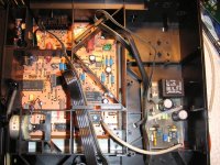
Franz, your 230 VAC looks not 100% good, it might even be dangerous. The creapage distance is way too small between primary and secondary side. You should strive to have 8 mm creapage.
Don't forget that your text is also made of copper so it will also decrease the general creapage.
BTW:
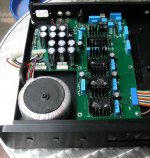
My next project, a external DAC with tube output, will be based on this Classé 1 enclosure with the original psu (the original dac board has burned out...).
Here, I find primary traces 4 to 5 mm away from the groundplane. And: originally, the middle pin of the IEC connector, the earth, is hanging in the air, not connected at all!
But: still a very nice base to build a own DAC. 10mm alu frontplate and very nice finish at all.
Franz
Attachments
Franz G said:
And: originally, the middle pin of the IEC connector, the earth, is hanging in the air, not connected at all!
That is called double insulated in Europe, nothing wrong with that. No ground loops and safe if well implemented.
- Status
- Not open for further replies.
- Home
- Source & Line
- Digital Line Level
- Can someone send to me the Elso's latest clock schematics (version6)? :)