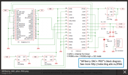
I guess this is the schematic you are referring. See the attached .png file.Maybe it can help, there is a schematics of I2S hifiberry DAC PRO for raspberry pi with 2 external clocks (depends of the frequency : 44.1 kHz or 48 kHz)
HiFiBerry DAC+ PRO????????? - nabe????
X44 is a 44.1 kHz x 512 = 22.5792 MHz quartz oscillator with an enable pin.
X48 is a 48.0 kHz x 512 = 24.5760 MHz quartz oscillator with an enable pin.
They both feed the SCK pin (aka MCLK) of the PCM5122 DAC.
You may rely on something like this.
In case of relying on a STM32F7 SAI(SPDIFTX) that you want to define as Master Audio Clock, a frequency division by 8 is required for getting 3.0720 MHz from 24.5760 MHz. You then provide the 3.0720 MHz to the STM32F7 "Audio Clock In" aka I2S_CKIN. Easy made, using three D-type flip-flops in series.
Be warned that such clocking is incompatible with the USB Audio Isochronous modality. Being fixed, your 3.0720 MHz Master Audio Clock is incapable of absorbing the (possibly very thin) frequency difference showing between the FS (eventually plagued with some jitter) imposed by the USB audio Isochronous source (a PC) and the local FS (of high quality) that you impose on the SAI(SPDIFTX). This may work a few seconds or a few minutes, the time you get stuck into a buffer underrun, or a buffer overflow.
You may get this working thanks to a quick and dirty fix.
Try continuously measuring the buffer underrun trend or buffer overflow trend, on the long term, before actually getting stalled into it. Drop or repeat one audio sample from time to time, whenever required for avoiding becoming stalled into a buffer underrun, or a buffer overflow.
This is a quick and dirty fix.
Have you noticed, as soon as you ask STM32CubeMX to enable the STM32F7 USB, you must hook a 16 MHz quartz on the two pins forming the High Speed External (HSE) oscillator. Why a 16 MHz quartz, and why not the High Speed Internal (HSI) Resistor-Capacitor (RC) 16 MHz clock ?
Answer : this is caused by the USB subsystem, requiring a precise quartz-based 48 MHz clock. STM32CubeMX is quite proactive, remembering you this.
Now that you are forced to rely on such 16 MHz quartz, why not try relying on it, and on the STM32F7 clock multipliers and dividers, for getting the required FS * 64 (of high quality) that you want to impose on the SAI(SPDIFTX) ?
Okay, try this, ONLY in case you trust the STM32F7 clock multipliers and dividers, which means they should NEVER produce hiccups when the software happens to do "this or that" like serving an interrupt or like getting close to congestion, and NEVER produce hiccups albeit the STM32F7 internal power supply potentially becoming noisy. Think about PLLM (a frequency divider) being obliged to output a low frequency in the order of 1 MHz to 2 MHz, that's getting PLL-multiplied by a vast amount, say 192 into PLLSAI, before becoming divided by 4 then 25, for delivering the FS * 64 to the SAI(SPDIFTX) corresponding to 3.0720 MHz for a 48 kHz FS.
Please refer to the STM32CubeMX sketch (.ioc file) that I have previously published.
Okay, if you trust all STM32F7 frequency multipliers and frequency dividers, you may rely on the 16 MHz quartz (HSE) for generating the FS * 64 to the SAI(SPDIFTX) corresponding to 3.0720 MHz for a 48 kHz FS.
But wait a minute, how to get the FS * 64 to the SAI(SPDIFTX) corresponding to 2.8224 MHz for a 44.1 kHz FS ?
We may try multiplying the PLLM frequency by 176 (instead of 192) in which case at the very end we get 2.8160 MHz instead of the required 2.8224 MHz. The SAI(SPDIFTX) will operate at 44.0 kHz instead of the required 44.1 kHz. Most devices connecting on the SPDIFTX won't sync. Such is the issue. It is a fatal issue, in case you wish to be 44.1 kHz compatible.
Anyway, relying on the 16 MHz HSE oscillator quartz, and on a chain of fixed-ratio frequency multipliers and frequency dividers, we have no chance of absorbing the (possibly very thin) frequency difference showing between the FS (eventually plagued with some jitter) imposed by the USB Audio Isochronous source (a PC) and the local FS (of high quality) that you impose on the SAI(SPDIFTX).
You may get this working thanks to a quick and dirty fix.
During USB Audio Isochronous playback, try continuously measuring the buffer underrun trend or buffer overflow trend, on the long term, before actually getting stalled into it. Increase or decrease the PLLSAI multiplication factor from time to time, whenever required for avoiding becoming stalled into a buffer underrun, or a buffer overflow.
This is a quick and dirty fix.
Now you know why it is advisable (however more complicated, however not an universal panacea) to rely on separate audio oscillators (22.5792 MHz and 24.5760 MHz), then add three D-type flip-flops in series for dividing them by 8, for feeding the STM32F7 "Audio Clock In" aka I2S_CKIN.
When your system must work in USB Audio Isochronous mode, the universal panacea is to rely on two discrete homemade inexpensive quartz-based oscillators (11.2896 MHz and 12.2880 MHz) divided by 4 (two D-type flip-flops) feeding the STM32F7 "Audio Clock In" aka I2S_CKIN, for clocking the SAI(SPDIFTX) at 3.0720 MHz (48 kHz FS) and 2.8224 MHz (44.1 kHz FS).
The oscillators must be discrete and homemade, in order the system to fine-tune their oscillation frequency using a Varicap diode.
Nowadays the Toshiba 1SV305 Varicap is widely available, kind of old days BB104, albeit requiring a lower voltage and featuring an improved capacitance ratio.
The 1SV305 Varicap datasheet is here : http://www.mouser.com/ds/2/408/DST_1SV305-TDE_EN_1341-736624.pdf
Such Varicap diode acts a variable 6 pF to 18 pF capacitor, depending on the reverse DC bias voltage that's applied on it. Using a STM32F7 PWM output and a 1 Hz lowpass filter, you will increase or decrease a DC voltage output, proportional to the buffer underrun / overflow trend. Such DC voltage to get amplified (min 1 VDC, max 4 VDC) and applied to the Varicap, as reverse bias voltage, for implementing a high-quality analog PLL, tracking the USB FS * 64.
No more a quick and dirty fix like dropping or repeating one audio sample from time to time.
No more a quick and dirty fix like increasing or decreasing the PLLSAI multiplication factor from time to time.
When your system must work in USB Audio Asynchronous mode, there is no need for a Varicap frequency control. In such modality, you need to set the STM32F7 PWM to some fixed value, that you determine using a frequency meter, for generating the exact nominal FS. Such frequency meter may be part of the STM32F7, using the built-in 16 MHz quartz (HSE) as timebase / gating and one of the many TIMER inputs (TIM1 ... TIM14) as hardware counter.
Now this being said, I went looking to the source code generated by STM32CubeMX, when enabling the USB_OTG_FS, and enabling the Middleware corresponding to the "Audio Device Class" what's regarding the USB_DEVICE FS IP.
The file usbd_audio.c says :
******************************************************************************
* @file usbd_audio.c
* @author MCD Application Team
* @version V2.4.2
* @date 11-December-2015
* @brief This file provides the Audio core functions.
*
* @verbatim
*
* ===================================================================
* AUDIO Class Description
* ===================================================================
* This driver manages the Audio Class 1.0 following the "USB Device Class Definition for
* Audio Devices V1.0 Mar 18, 98".
* This driver implements the following aspects of the specification:
* - Device descriptor management
* - Configuration descriptor management
* - Standard AC Interface Descriptor management
* - 1 Audio Streaming Interface (with single channel, PCM, Stereo mode)
* - 1 Audio Streaming Endpoint
* - 1 Audio Terminal Input (1 channel)
* - Audio Class-Specific AC Interfaces
* - Audio Class-Specific AS Interfaces
* - AudioControl Requests: only SET_CUR and GET_CUR requests are supported (for Mute)
* - Audio Feature Unit (limited to Mute control)
* - Audio Synchronization type: Asynchronous
* - Single fixed audio sampling rate (configurable in usbd_conf.h file)
* The current audio class version supports the following audio features:
* - Pulse Coded Modulation (PCM) format
* - sampling rate: 48KHz.
* - Bit resolution: 16
* - Number of channels: 2
* - No volume control
* - Mute/Unmute capability
* - Asynchronous Endpoints
*
* @note In HS mode and when the DMA is used, all variables and data structures
* dealing with the DMA during the transaction process should be 32-bit aligned.
*
*
* @endverbatim
*
******************************************************************************
Why do they write " Audio Synchronization type: Asynchronous".
Can somebody tell ?
What Audio Synchronization are they talking about ?
Is it the software synchronization between the usb engine (middleware), and the application ?
See the attached .zip file.
This is the code generated by STM32CubeMX when enabling the USB_OTG_FS, and enabling the Middleware corresponding to the "Audio Device Class" what's regarding the USB_DEVICE FS IP.
Regards,
Steph
Attachments
Last edited:
You are right, All FDA are class D amplifier. It means they work with analog signals.
The difference with other class D amps is they have inside their chip a class D amplifier of course, a DAC to convert the digital data to analog, and a PWM converter. It is a way to offer to people integrated technology....
FDAs are like laptops with screen and keyboard provided....
other class D are like desktop computers... You can change components as you want (advantage). But it is bigger and less 'user friendly' (not good).
Choice is yours 🙂
I understand. I would be very happy to know if, difgging in the fine details, a FDA is a DAC+Analog to PWM+Power stage, with the same exact architecture and technology as a dedicated DAC (ie putting on the same silicon the 2 components), or if the fact that I2S to PWM is needed allows for simplifications, optimizations, has some edge on some way.
However, some of those FDA souds pretty good and simplifies the design.
JMF
RPI or ODROID C2 are good choices 🙂
But why USB and not I2S?
In fact, I'm already running my MPD sever on an Orange Pi.
I look at USB over I2S, hoping to succeed to have a true async USB that will allow to decouple the two time domains. STM32 controlling the flow on the USB side, and playing the samples with its internal clock.
If we have I2S input, we have to deal with the 2 time domains...
I don't know if it would be easy to have the Orange Pi play through I2S in slave mode. This would be an interesting option.
JMF
@steph_tsf
Thank you for all the analysis. This week is very busy and I don't progress fast on the USB front. I have the USB lib manual with me and study it. They implement the quick and dirty fix to manage the differences of times (add or delete samplers based on buffer filling). My idea is to implement their lib, and try to track how frquently they have to adjust, to see if it is acceptable or not. I have also spotted some code to study for clean async implementation with control flow for a PIC32. To study later...
I would be the happiest to implement a good clock in my project as long as:
- cost would not be above the one of the nucleo board (shipping included),
- I don't have to design anything, as I don't have the knowledge,
- no PCB specifc design and manufacturing,
- no components impossible to solder because of size and so on.
If a schematic and BOM is provided and physical/practical implementation is easy on a nucleo board, I will jump on it.
Last, from what I understand, the HSE crystal on the nucleo board is 8 Mhz (16 Mz being a factor 2).
More about Voltage Controlled Xtal Oscillators (VCXO).
You can find them here :
22.5792 MHz : http://eu.mouser.com/Passive-Components/Frequency-Control-Timing-Devices/Oscillators/VCXO-Oscillators/_/N-7jdks?P=1z0wnr9
24.5760 MHz : http://eu.mouser.com/Passive-Components/Frequency-Control-Timing-Devices/Oscillators/VCXO-Oscillators/_/N-7jdks?P=1z0wnsv
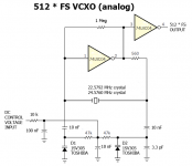
Some VCXOs are analog, featuring a fundamental mode quartz inside that's loaded by varicap diodes. Look the Pletronics datasheet.
http://www.mouser.com/ds/2/326/vha6%203.3v-4748.pdf
They consume approx 5 mA from the power supply.
Attached is a .png of what's inside such Pletronics VCXO. Nothing complicated here.
Some VCXOs are digital, relying on a DSPLL clock synthesis, featuring a fixed frequency quartz inside followed by a Direct Digital Synthesis. Look the Silicon Labs datasheet.
http://www.mouser.com/ds/2/368/Si552-52721.pdf
They consume approx 100 mA from the power supply.
My preference goes to the analog variety (Pletronics).
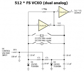
One may rely on a 74LVC4066 quad bilateral analog switch, for selecting the quartz that's actually connecting to the oscillator circuitry. Only one oscillator circuitry.This would be simple and elegant. Look the datasheet.
http://www.mouser.com/ds/2/302/74LVC4066-839854.pdf
Attached is a .png of what could be a '"dual analog" VCXO relying on a 74LVC4066 quad bilateral analog switch.
Cheers,
Steph
You can find them here :
22.5792 MHz : http://eu.mouser.com/Passive-Components/Frequency-Control-Timing-Devices/Oscillators/VCXO-Oscillators/_/N-7jdks?P=1z0wnr9
24.5760 MHz : http://eu.mouser.com/Passive-Components/Frequency-Control-Timing-Devices/Oscillators/VCXO-Oscillators/_/N-7jdks?P=1z0wnsv
Some VCXOs are analog, featuring a fundamental mode quartz inside that's loaded by varicap diodes. Look the Pletronics datasheet.
http://www.mouser.com/ds/2/326/vha6%203.3v-4748.pdf
They consume approx 5 mA from the power supply.
Attached is a .png of what's inside such Pletronics VCXO. Nothing complicated here.
Some VCXOs are digital, relying on a DSPLL clock synthesis, featuring a fixed frequency quartz inside followed by a Direct Digital Synthesis. Look the Silicon Labs datasheet.
http://www.mouser.com/ds/2/368/Si552-52721.pdf
They consume approx 100 mA from the power supply.
My preference goes to the analog variety (Pletronics).
One may rely on a 74LVC4066 quad bilateral analog switch, for selecting the quartz that's actually connecting to the oscillator circuitry. Only one oscillator circuitry.This would be simple and elegant. Look the datasheet.
http://www.mouser.com/ds/2/302/74LVC4066-839854.pdf
Attached is a .png of what could be a '"dual analog" VCXO relying on a 74LVC4066 quad bilateral analog switch.
Cheers,
Steph
Attachments
Last edited:
I was not aware of this, as it doesn't show in the AN1422A. See the attached .pdf. A clean USB Audio Async implementation with control flow for a STM32F4 or STM32F7 would be an essential brick, of great value. Most projects fail, because of the USB enumeration issue. Will you end up developing and publishing a specific driver for Windows / Android / iOS / MacOS. Ough !I have also spotted some code to study for clean USB Audio Async implementation with control flow for a PIC32. To study later...
Attachments
I was not aware of this, as it doesn't show in the AN1422A. See the attached .pdf. A clean USB Audio Async implementation with control flow for a STM32F4 or STM32F7 would be an essential brick, of great value. Most projects fail, because of the USB enumeration issue. Will you end up developing and publishing a specific driver for Windows / Android / iOS / MacOS. Ough !
Those are links I had found about an implementation of the USB async control flow on PIC32:
http://www.microchip.com/forums/m547546.aspx
http://www.microchip.com/forums/m424170-p2.aspx
Normally no need to develop window/Mac/Linux drivers as the feature is already implemented. This is why Async USB DAC can be plug and play.
JMF
I understand. I would be very happy to know if, difgging in the fine details, a FDA is a DAC+Analog to PWM+Power stage, with the same exact architecture and technology as a dedicated DAC (ie putting on the same silicon the 2 components), or if the fact that I2S to PWM is needed allows for simplifications, optimizations, has some edge on some way.
JMF
Difficult to say.... There are copyrights and we only have functional architecture documents.... We can suspect some components optimization.
If your question is quality oriented, definitely, it is possible to achieve better quality with a regular class D amplifier, a raspberry pi and a DAC (like a desktop computer). But simplicity, price and size are not the same.
1. Before you step into this, try measuring and documenting the performance (in term of buffer underrun / overflow syndrom) of a bare USB Audio Isochronous implementation, when connecting various audio USB sources (PC XP, PC Win7, MacOS, iOS, Android) on the STM32 Nucleo board. Try to understand the STM32 source code, so you can edit it for disabling / enabling any quick and dirty fix that may exist over there, like repeating / dropping audio samples or like increasing / decreasing the audio PLL frequency multiplier or divider. Try measuring and documenting the performance (in term of buffer underrun / overflow syndrom) when disabling / enabling the quick and dirty fix that may exist over there. Using a counter, tell us how many glitches per hour, knowing we won't waste much time at this stage, in discriminating between inaudible glitches, barely audible glitches, and audible glitches.Those are links I had found about an implementation of the USB async control flow on PIC32:
bare minimum audio endpoint with rate feedback example | Microchip
Asynchronous OUT endpoint with rate feedback? | Microchip
Normally no need to develop window/Mac/Linux drivers as the feature is already implemented. This is why Async USB DAC can be plug and play.
JMF
2. Try summarizing in a text description, less than 20 lines long, the working of the so-called "audio Isochronous sink endpoint with feedback" aka "Isoc Async sink" that got initiated by sc6po (in 2009 ?), then streamlined by stefanopod in Jan 2011. Compare such "Isoc Async sink" to the "original Isoc sink" known to produce jitter unless there is a FIFO and some accurate audio reclocking inside the audio sink like the PCM2702 USB Audio DAC does.
This is here, just like you pointed out : bare minimum audio endpoint with rate feedback example | Microchip
3. Try summarizing in a text description, less than 20 lines long, why on post #18, chinzei starts arguing that such "Isoc Async sink" is non-standard and more complicated than the "original Async sink" that's described in the USB spec, assigning a simple comparator role to the device in the feedback loop.
4. Try deciding what USB audio implementation you are willing to adopt :
(a) the original "Isoc sink" assorted to a FIFO enabling audio sample repeat/drop,
(b) the original "Isoc sink" assorted to a FIFO and a PLL multiplication/division factor increase/decrease,
(c) the original "Isoc sink" assorted to a FIFO and a VCXO able to lock on the long term USB sampling frequency,
(d) the "Isoc Async sink" featuring the rate feedback mechanism described by sc6po & stefanopod,
(e) the "original Async sink" that's described in the USB spec, assigning a simple comparator role to the device in the feedback loop.
5. Try justifying your choice, in terms of targeted audio accuracy, accepted complexity, and the desired PC XP, PC Win7, MacOS, iOS, Android plug-and-play feature (no specific driver required).
6. Ask yourself, if you have enough time and experience for dealing with this.
7. Consider the software development time you can spare by grabbing stereo audio from I2S thanks to a miniDSP miniStreamer hooked on a PC or a Mac. See this here : https://www.minidsp.com/products/usb-audio-interface/ministreamer
8. Using the STM32CubeMX and a Nucleo144 F746, check the feasibility of an arrangement consisting of a miniDSP miniStreamer feeding the STMF746 SAI1A(I2SRX), while on the other side, the STMF746 SAI2A(SPDIFTX) and SAIT2B(SPDIFTX) are feeding two TOPPING VX2 spdif-in stereo power amplifiers.
9. Using the STM32CubeMX and a Nucleo144 F746, check the feasibility of an arrangement consisting of a miniDSP miniStreamer feeding the STMF746 I2S1(RX), while on the other side, the STMF746 I2S2(TX) and I2S3(TX) are feeding a TDA7801 (4-channels I2S-in power amp).
10. Using the STM32CubeMX and a Nucleo144 F746, check the feasibility of an arrangement consisting of a miniDSP miniStreamer feeding the STMF746 SAI1A(I2SRX), while on the other side, the STMF746 SAI2A(TDMTX-4ch) is feeding a TDA7801 (4-channels TDM-in power amp), and SAI2B(TDMTX-4ch) is feeding a TDA7801 (4-channels TDM-in power amp).
Cheers,
Steph
Last edited:
I'm suggesting something like the attached .zip file (contains the .ioc file).Using the STM32CubeMX and a Nucleo144 F746, check the feasibility of an arrangement consisting of a miniDSP miniStreamer feeding the STMF746 SAI1A(I2SRX), while on the other side, the STMF746 SAI2A(TDMTX-4ch) is feeding a TDA7801 (4-channels TDM-in power amp), and SAI2B(TDMTX-4ch) is feeding a TDA7801 (4-channels TDM-in power amp).
Cheers,
Steph
Attachments
Hi JMF,
Firstly I have to say I don't know if it is so important to have an external clock as a lot of modern DACs have jitter correction embedded. There is no formal studies about benefits or not. Hifiberry for this excellent DAC say on its website it is not sure the PRO version of this DAC (with the external clocks) improve the quality.
Having a second thought, and for my specific (short term) need, I may not need an external clock. I want to use my FX-Audio D802 amps through the SPDIF line that relies on a AK4113 (no easy tweak yet to go directly to the I2S input). So I will have go through the AKM AK4113 and this one has an integrated low jitter PLL.
At this stage, I will try to stick with the onboard 8 Mhz oscillator (except if I can find a much better HSE frequency that would match USB and SPDIF needs and be implemented on the nucleo board).
I will also define if I will use 44.1 or 48 kHz and will stick to that. I will resample in the MPD server.
JMF
JMF
Last edited:
Small update.
I now have the USB audio in=>I2S=>DAC working. It took more than I expected, but I finally succeeded to translate an example from one of the other evaluation boards to the stm32F4_Dicovery board. I had difficulties to set all dependencies right, with my inexperience with Eclipse, the IDE used by openStm32.
Next step is to merge the two projects, and achieve the USB audio in=>DSP=> I2S=>DAC
I have also found some additional discussions about feedback implementation in USB Async Audio.
JMF
JMF
Small update.
I now have the USB audio in=>I2S=>DAC working. It took more than I expected, but I finally succeeded to translate an example from one of the other evaluation boards to the stm32F4_Dicovery board. I had difficulties to set all dependencies right, with my inexperience with Eclipse, the IDE used by openStm32.
Next step is to merge the two projects, and achieve the USB audio in=>DSP=> I2S=>DAC
I have also found some additional discussions about feedback implementation in USB Async Audio.
JMF
JMF
Thanks for the update, exciting stuff!
Did you accomplish this in code only, using the physical components already present on the stm32F4_Dicovery board?
Are you pushing your code to GitHub or other public repo/svn?
Thx for all of the info!
Are you getting one interrupt per newly available audio sample, or one interrupt per newly available audio buffer?Next step is to merge the two projects, and achieve the USB audio in=>DSP=> I2S=>DAC
How deep is the audio buffer?
Does the audio DSP occur inside an interrupt routine (in which case you incur some heavy context save/restore), or does the audio DSP occur in the main_loop under a flag that's getting polled?
Thanks for the update, exciting stuff!
Did you accomplish this in code only, using the physical components already present on the stm32F4_Dicovery board?
Are you pushing your code to GitHub or other public repo/svn?
Thx for all of the info!
Yes, this is code only. I don't push the code to Github on a regular basis by lack of knowledge about Eclipse and how the synchronize with GitHub.
I will upload a next version of the sources once I will have something satisfying with a chain USBB=>DSP=I2S=> DAC.
I worked several hours yesterday to achieve that, and let's say that I don't like the implementation of the Audio USB Device lib provided by ST. It may be good enough for playing directly from the USB, but is not suitable for DSP filtering. I looked hard about how to deal with proposed functions from the lib (only working in callback functions), but concluded at the end that small modifications would be much better. However as all code is available, I have some idea about how to adapt it.
JMF
Are you getting one interrupt per newly available audio sample, or one interrupt per newly available audio buffer?
How deep is the audio buffer?
Does the audio DSP occur inside an interrupt routine (in which case you incur some heavy context save/restore), or does the audio DSP occur in the main_loop under a flag that's getting polled?
In ST lib, there is a callback at the end of a USB frame (1ms of samples), but as implemented, I can't get the action I want there. I will modify it slightly.
My intention is to implement the audio DSP in the main, which also requires some adaptation of the ST code (expected structure would be similar to the one I uploaded on Github).
JMF
I now have the USB audio in=>I2S=>DAC working. It took more than I expected, but I finally succeeded to translate an example from one of the other evaluation boards to the stm32F4_Dicovery board. I had difficulties to set all dependencies right, with my inexperience with Eclipse, the IDE used by openStm32.
Congratulations!
If you aren't pushing to GitHub frequently, I hope you have good backups so you don't loose work when the rare, inevitable happens.
Congratulations!
If you aren't pushing to GitHub frequently, I hope you have good backups so you don't loose work when the rare, inevitable happens.
This is the frustrating part: being inexperienced in the tools and loosing time on that side instead of developping the application...
Any help to set-up the thing correctly in order to share the code, have the back-up and allow shared development would be highly appreciated.
By the way, yesterday I found what I was looking for to be confident in deing able to develop the Async USB with explicit feedback, which was my main concern. Really good news !!!
And it derives from work partially done here... at DIYaudio 🙂 in the Audio-widget project.
JMF
Dear Steph_TSF and others,
I would need your help for a future move forward for the project. It seems that you have studied a lot the clock schemes for the stm32 boards. On my side, I started to use the CubeMX tool and I'm not comfortable with the outcomes. I also don't succeed to understand all the crystal choice discussions in https://www.politesi.polimi.it/handle/10589/72062 (thesis can be downloaded) between 12.288 MHz and 14.7456MHz crystals) and don't how to achieve good accuracy with their design choices.
The two below configurations need to be investigated:
At the moment, I discard the external audio clock option as I don't know how to implement it easily and not slow down the project. I also think that I don't need it for my purpose. Having the an Async USB avoids the 2 clock domains. The remaining is acceptably correct replay pace (I imagine that below 1% is acceptable) and Jitter.
Would you be able to develop 2 clock schemes for this board.
Scheme 1: Use existing 8Mz crystal, OK for Audio USB, generates Master clock, Accurate for 44.1 KHz I2S, Accurate for 44.1 KHz SPDIF
Scheme 2: Use additional X3 crystal for HSE, identify the most suitable frequency, OK for Audio USB, generates Master clock, Accurate for 44.1 KHz I2S, Accurate for 44.1 KHz SPDIF.
Note: I choose 44.1Hz sampling rate as it is consistent with the huge majority of the audio materials. I can resample upstream the other sampling rates
But if for some reason the clocks accuracy was much better with the 48 MHz, please let me know.
Help on that specific scope would be much appreciated.
JMF
I would need your help for a future move forward for the project. It seems that you have studied a lot the clock schemes for the stm32 boards. On my side, I started to use the CubeMX tool and I'm not comfortable with the outcomes. I also don't succeed to understand all the crystal choice discussions in https://www.politesi.polimi.it/handle/10589/72062 (thesis can be downloaded) between 12.288 MHz and 14.7456MHz crystals) and don't how to achieve good accuracy with their design choices.
The two below configurations need to be investigated:
- Nucleo stm32F7 using onboard 8MHz Crystal for HSE,
- Nucleo stm32F7 using additional X3 Crystal for the HSE clock, freq to be defined. There is a place holder on the Nucleo board for such oscillator
At the moment, I discard the external audio clock option as I don't know how to implement it easily and not slow down the project. I also think that I don't need it for my purpose. Having the an Async USB avoids the 2 clock domains. The remaining is acceptably correct replay pace (I imagine that below 1% is acceptable) and Jitter.
Would you be able to develop 2 clock schemes for this board.
Scheme 1: Use existing 8Mz crystal, OK for Audio USB, generates Master clock, Accurate for 44.1 KHz I2S, Accurate for 44.1 KHz SPDIF
Scheme 2: Use additional X3 crystal for HSE, identify the most suitable frequency, OK for Audio USB, generates Master clock, Accurate for 44.1 KHz I2S, Accurate for 44.1 KHz SPDIF.
Note: I choose 44.1Hz sampling rate as it is consistent with the huge majority of the audio materials. I can resample upstream the other sampling rates
But if for some reason the clocks accuracy was much better with the 48 MHz, please let me know.
Help on that specific scope would be much appreciated.
JMF
Please review the six clock schemes inside the attached .zip.Would you be able to develop 2 clock schemes for this board.
Attachments
- Home
- Source & Line
- Digital Line Level
- Can low jitter be achieved with STM32 microcontroller