Hi Steph and all,
I already need your help. I'm at the bottom of the earning curve and I block on the first issue. Maybe you could have the look and help. I attach my project.
https://dl.dropboxusercontent.com/u/29484066/Templates.zip
This is an openStm32 project. I did not included the driver and HAL files from Stm32cubeF4
It is intended to run on a Stm32F4 Discovery . I tried to develop the first part of the application: read the table (PCM) in Fragment1.h and play it on the board DAC, using the libraries from Driver/BSP: stm32f4_discovery_audio
The example Audio_playback_and_record for the board, in Stm32cubeF4 works, but is very complex and difficult to understand. The one propsosed with http://www.st.com/content/st_com/en.../stm32-ode-translate-hw/x-nucleo-cca01m1.html is much better builtand easier to understand and build on top, but it doesn't exists for the Stm32F4-Discovery.
To make it simple, as a first trial, all the code is in main.c and stm32f4xx_it.c (and associated .h when needed)
I succeed to intialize the audio output and start the play. The buffer callbacks are periodically actuated, but I have only strange noise in the earspeakers connected to the DAC.
Would you have an idea why I don't get "structured sound" ?
I will be on leave for coming days with limited assess to my internet, but will try to browse the forum from time to time.
Best regards and tahns a lot to anybody that could help.
JMF
Hi,
Small update. I could work a bit during the last days, and the first step is achieved. I can play my buffer in the board DAC, through I2S, with clean code.
Next step is to add some some DSP, applying biquad filters to the buffer.
Best regards,
JMF
Small update. I could work a bit during the last days, and the first step is achieved. I can play my buffer in the board DAC, through I2S, with clean code.
Next step is to add some some DSP, applying biquad filters to the buffer.
Best regards,
JMF
Just found this thread.. I, too, am working on a DSP project using the STM32F767ZI.
I'm using the AD1938 as my audio codec IC: http://www.analog.com/en/products/audio-video/audio-codecs/ad1938.html#product-overview
It's perhaps a little overkill but I dread developing a solution that, in the end, isn't quite good enough.
I intend to develop a solution that, in the end, accepts 4 analog inputs and provides 8 analog outputs.
I'm going to be reading this thread closely. I'll post any useful information I have to share!
Willing to design a stackable $129 "audio 4.8 cape" hosting a AD1938 hooked on SAI1/TDM, and perhaps also a WM8804 (SPDIF-in and SPDIF-out) hooked on SAI2/I2S ? Adding a 12.288 MHz quartz acting as audio master clock when the system is grabbing audio from USB-Async or from Analog-in ? No ASRC ?Just found this thread. I, too, am working on a DSP project using the STM32F767ZI. I'm using the AD1938 as my audio codec IC. I intend to develop a solution that, in the end, accepts 4 analog inputs and provides 8 analog outputs. I'm going to be reading this thread closely. I'll post any useful information I have to share!
Willing to design a stackable $129 "audio 4.8 cape" hosting a AD1938 hooked on SAI1/TDM, and perhaps also a WM8804 (SPDIF-in and SPDIF-out) hooked on SAI2/I2S ? Adding a 12.288 MHz quartz acting as audio master clock when the system is grabbing audio from USB-Async or from Analog-in ? No ASRC ?
So that's definitely a possibility.
The only possible risk factors there would be that I have some fairly specific design goals and environmental requirements due to my intended application, namely, Car Audio.
I'm experimenting with ways to isolate the Input/Output (analog) stage from the rest of the howling RF mess that is a MCU board/ecosystem. Given that I'm using a codec chip with the ADCs and DACs on the same silicon, it may be a fool's errand, but I'm still investigating.
I am also planning on, initially, using the AD1938's internal clock as my audio master, trying to keep the component count as low as possible. If that proves insufficient, I'll use a crystal oscillator of an appropriate value.
As far as selling it... We'll see? I had never planned on having a true 'User Interface' for my solution, relying instead on settings and parameters riding in the code at compile time. That said, I'm definitely open to the idea of providing such an interface in one way or another. Unless the MCU has ample headroom remaining after performing the DSP functions (a fact I'm not betting on), I'll probably engineer the interface using an additional MCU with appropriate control connections into the DSP. This may be transparent to the user, ie, housed inside the same box with no physical separation at all. It may also be completely separate, requiring the user to attach it to the DSP unit for configuration activities.
My professional background is more in Enterprise IT and Software Development, so my "run home to momma" instinct is to set up a NodeJS server with a web interface for configuration...but that may be a bit heavy for an MCU! hahaha
Anyway, any time I'm designing something, I always try and make it as modular or generalized as is practical, so by the time I am sending off the gerber files for the custom PCBs, we may have a "shield" that can just be snapped onto the STM32F767ZI-NUCLEO board, or we may have something only a mother could love. We'll see!
I'll post any new findings or developments if they might be helpful to others here, I'll definitely have questions for some of the more experienced users here.
Thanks!
The audio shield may host a wireless interface (WiFi or Bluetooth) hooked on a Cortex-M7 serial interface (Tx/Rx). Viewed from outside, your DSP application can appear as a device containing register files. Say a register file containing all left channel IIR BiQuad coefficients. Say another register file containing all left channel FIR filter coefficients. Some more registers for defining the volumes. The Tx/Rx interface handles ascii messages from a computer, tablet, or smartphone. The format can be : special character (notifies the start of a new message), two ascii characters (this is the opcode), data (many ascii characters), special character (notifies the end of the message). You can start writing values in tables like for editing the IIR Biquad filter coefficients, and the FIR filter coefficients. You can add some more control registers like volume control registers. You can add more control registers like enabling block diagram A or enabling block diagram B. In case the controlling device is a PC or a tablet, your controlling app can show a nice block diagram having editable fields. Possibly you'll end up defining a powerful message enabling to install pre-compiled DSP code.My professional background is more in Enterprise IT and Software Development, so my "run home to momma" instinct is to set up a NodeJS server with a web interface for configuration...but that may be a bit heavy for an MCU! hahaha
The AD1938 datasheet says :The only possible risk factors there would be that I have some fairly specific design goals and environmental requirements due to my intended application, namely, Car Audio. I'm experimenting with ways to isolate the Input/Output (analog) stage from the rest of the howling RF mess that is a MCU board/ecosystem. Given that I'm using a codec chip with the ADCs and DACs on the same silicon, it may be a fool's errand, but I'm still investigating. I am also planning on, initially, using the AD1938's internal clock as my audio master, trying to keep the component count as low as possible. If that proves insufficient, I'll use a crystal oscillator of an appropriate value.
By using the on-board PLL to derive the master clock from the LR clock or from an external crystal, the AD1938 eliminates the need for a separate high frequency master clock and can also be used with a suppressed bit clock.
Which means that YOU need to define the audio master clock, somewhere. The AD1938 PLL is only there for generating some internal MCLK, in case no MCLK is supplied to the AD1938, or in case the MCLK that's supplied to the AD1938 is of poor quality.
A quartz is thus always required.
In case you hook the quartz very close to the AD1938, delivering a high quality MCLK to the AD1938, the AD1938 PLL can be bypassed (there is a register to be written).
The quartz needs to be the audio master clock, when your system is grabbing audio from the analog inputs, or when your system is grabbing audio from USB-audio-async.
In case your system is grabbing audio from USB-audio-sync, the quartz cannot be the audio master clock. This time, your system must accompany the USB-audio clock the best it can, knowing that such clock will depart from the quartz. You need to implement a kind of PLL using software, that's independent from the quartz. This is difficult. Very few succeed into this. When they understand the problem, they add a hardware-ASRC.
In case your system is grabbing audio from SPDIF, the quartz cannot be the audio master clock. This time, your system must accompany the SPFIF audio clock the best it can, knowing that such clock will depart from the quartz. Fortunately all SPDIF receivers embed a PLL able to follow the SPDIF audio clock, possibly delivering a high quality re-generated MCLK and LRCK that you can provide to the AD1938. This is less difficult. You just need a 2-1 selector, for telling your system who is the master audio clock.
A chip like the WM8580 (audio hub, 2 channels-in, 6 channels-out, SPDIF-in, SPDIF-out) has everything built-in. Consider such chip, for simplicity.
Regards,
Steph
The AD1938 datasheet says :
By using the on-board PLL to derive the master clock from the LR clock or from an external crystal, the AD1938 eliminates the need for a separate high frequency master clock and can also be used with a suppressed bit clock.
Which means that YOU need to define the audio master clock, somewhere. The AD1938 PLL is only there for generating some internal MCLK, in case no MCLK is supplied to the AD1938, or in case the MCLK that's supplied to the AD1938 is of poor quality.
A quartz is thus always required.
In case you hook the quartz very close to the AD1938, delivering a high quality MCLK to the AD1938, the AD1938 PLL can be bypassed (there is a register to be written).
The quartz needs to be the audio master clock, when your system is grabbing audio from the analog inputs, or when your system is grabbing audio from USB-audio-async.
In case your system is grabbing audio from USB-audio-sync, the quartz cannot be the audio master clock. This time, your system must accompany the USB-audio clock the best it can, knowing that such clock will depart from the quartz. You need to implement a kind of PLL using software, that's independent from the quartz. This is difficult. Very few succeed into this. When they understand the problem, they add a hardware-ASRC.
In case your system is grabbing audio from SPDIF, the quartz cannot be the audio master clock. This time, your system must accompany the SPFIF audio clock the best it can, knowing that such clock will depart from the quartz. Fortunately all SPDIF receivers embed a PLL able to follow the SPDIF audio clock, possibly delivering a high quality re-generated MCLK and LRCK that you can provide to the AD1938. This is less difficult. You just need a 2-1 selector, for telling your system who is the master audio clock.
A chip like the WM8580 (audio hub, 2 channels-in, 6 channels-out, SPDIF-in, SPDIF-out) has everything built-in. Consider such chip, for simplicity.
Regards,
Steph
Hey there, thanks for all the good info!
At this time I have no interest in any digital inputs, I simply want a high quality ADC/DAC combo to pull the audio from my source and push it out after processing, so I should be able to clock it in the most efficient way possible.
Any other connectivity possibilities would be for a subsequent project, at this point.
Thanks again for the information!
Hi, Sh0velman I hope you will design a clean Nucleo "digital audio cape" hosting the AD1938 multichannel codec.
Please consider :
- the Nucleo-F446ZE (ARM Cortex-M4)
- the Nucleo-F746ZG (ARM Cortex-M7)
Both feature the same connectivity.
Try designing your AD1938 cape, allowing to stack two such capes.
- cape #1 will hook on SAI1(TDM) and SPI1
- cape #2 will hook on SAI2(TDM) and SPI2
Nucleo to feature :
- one GPIO (out) as cape #1 11.2896 MHz quartz oscillator enable
- one GPIO (out) as cape #1 12.2880 MHz quartz oscillator enable
- one GPIO (out) telling cape #1 to act as audio clock master or slave
- one GPIO (out) telling cape #2 to act as audio clock master or slave
Each AD1938 master-capable cape to feature :
- a 11.2896 MHz quartz oscillator possibly used as audio master clock (MCLK = 256 x 44.1 kHz) with 3-state enable pin
- a 12.2880 MHz quartz oscillator possibly used as audio master clock (MCLK = 256 x 48 kHz) with 3-state enable pin
- SAI1(TDM) and SPI1
- one GPIO (in) telling cape #1 to act as audio clock master or slave
Each AD1938 slave cape to feature :
- no quartz oscillator (de-populated stuff)
- SAI2(TDM) and SPI2
- no audio clock master possibility (de-populated stuff leading to always clock slave)
One can hook a WM8804 cape (SPDIF transceiver) instead of a AD1938 slave cape.
Such WM8804 cape to feature :
- the 12 MHz quartz feeding the auto-adaptive PLL, possibly used as audio master clock (MCLK = 256 x Fs) when the SPDIF-in gets selected as audio input
- SAI2 and SPI2
- one GPIO (in) telling cape #2 to act as audio clock master or slave
Regards,
Steph
Hi,
The second stage is achieved.On the stm32F4 discovery board, I can now:
- read the PCM 16 bit values,
- convert to float type,
- apply a biquad cascade (float32 type)
- convert back to PCM
- play to I2S and then to the DAC
Next stage is to set-up the USB audio class input, to get the full chain blocks.
Being a bit further on the learning curve helps. My C gets a bit better. I stuggle a bit with Eclipse but can perform the basic actions.
In parallel, I have to prepare the BOM for the Stm32F7 nucleo board. This a a topic were I'm not at ease, so any help would be appreciated to order all needed parts in one stop:
Identified:
- NUCLEO-F767Z,
- 210R, 110R resistors for the SPDIF output,
- 100 nF capacitors for SPDIF output,
- 2xCinch for SPDIF output,
- how to build an external audio clock for clean SPDIF or I2S clock (components/schematics/implementation or product)?
- power supply needed or USB power from Raspberry Pi should be sufficient?
- other components to source ?
Help welcomed,
Best regards,
JM
Hi,
The second stage is achieved.On the stm32F4 discovery board, I can now:
- read the PCM 16 bit values,
- convert to float type,
- apply a biquad cascade (float32 type)
- convert back to PCM
- play to I2S and then to the DAC
Next stage is to set-up the USB audio class input, to get the full chain blocks.
Being a bit further on the learning curve helps. My C gets a bit better. I stuggle a bit with Eclipse but can perform the basic actions.
In parallel, I have to prepare the BOM for the Stm32F7 nucleo board. This a a topic were I'm not at ease, so any help would be appreciated to order all needed parts in one stop:
Identified:
- NUCLEO-F767Z,
- 210R, 110R resistors for the SPDIF output,
- 100 nF capacitors for SPDIF output,
- 2xCinch for SPDIF output,
- how to build an external audio clock for clean SPDIF or I2S clock (components/schematics/implementation or product)?
- power supply needed or USB power from Raspberry Pi should be sufficient?
- other components to source ?
Help welcomed,
Best regards,
JM
JM, are you willing to share your source? I'd be interested to see what you've got so far.
Thanks!
Next stage is to set-up the USB audio class input, to get the full chain blocks. How to build an external audio clock for clean SPDIF or I2S clock (components/schematics/implementation or product)?
The SAI(in SPDIF TX protocol) requires a 256 x Fs clock divided by 4.
Which means for 48 kHz : 256 x 48 kHz (12.288 MHz) divided by 4 = 3.072 MHz.
USB Audio-isochronous : the USB is the audio master clock. Unfortunately it is of poor quality. Look the PCM2702 datasheet here : http://www.ti.com/lit/ds/symlink/pcm2702.pdf. As you can see, the USB writes data into a FIFO that gets read by a PLL whose frequency is managed in such a way that it corresponds to the USB audio frequency, only in the long term. Kind of smoothing and filtering. You can emulate this using a STM32F7, by realtime altering the PLL multiplier (in +1 or -1 discrete changes) that's in charge of generating the SAI(SPDIF) clock. Your criterion for speeding up / leaving intact / slowing down the SAI(SPDIF) clock, is the analysis of FIFO underrun trend / FIFO overflow trend in the long term. Be warned that in case the USB audio frequency is significantly departing from 44.1 kHz or 48 kHz, the SPDIF receivers connecting to your SAI(SPDIF) won't synchronize. On the other hand, rest assured that in case the machine that's generating the USB Audio-isochronous is decent, you won't get issues.
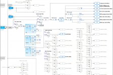
Here is the STMCubeMX sketch corresponding to this :
- 16 MHz quartz CPU clock (for precision)
- HSE clock selection
- PLLM / 10
- PLLN * 210
- PLLP / 2
- PLLQ /7 for getting the 48 MHz that's required for USB
- PLLCLK clock selection
- SYSCLK = 168 MHz (max is 216 MHz for the STM32F7)
- PLLSAI *192 (this is the one to be decremented by 1 or incremented by 1, acting as long term PLL)
- PLLSAIQ /4
- PLLSAIQDIV /25 for getting the 3.072 MHz that's required for 48 kHz audio on SAI(SPDIF)
- PLLSAIA as SAI1 audio clock source
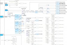
USB Audio-async : your SPDIF transmitter(s) shall act as audio clock master, explicitly requesting audio packets over USB. Your "audio shield" must feature the local high quality audio clock, 44.1 kHz or 48 kHz or both. There are 256 x Fs oscillators available, with an enable pin. As stated above, you need to divide the 256 x Fs clock by four, before applying it to the "Audio Clock Input" pin of the STM32F7.
Here is the STMCubeMX sketch corresponding to this :
- 16 MHz quartz CPU clock (for precision)
- HSE clock selection
- PLLM / 16
- PLLN * 384
- PLLP / 2
- PLLQ /8 for getting the 48 MHz that's required for USB
- PLLCLK clock selection
- SYSCLK = 192 MHz (max is 216 MHz for the STM32F7)
- a 12.288 MHz quartz / 4 = 3.072 MHz clock on the "Audio Clock Input" pin of the STM32F7
- I2S_CKIN as SAI1 audio clock source
Have a look to the attached files. The .ioc files are the STMCubeMX files. Double click on them and STM32CubeMX will start and load them.
Cheers,
Steph
Attachments
@stef_tsf: Thank you for all the information. I have to follow your route and study STM32CubeMX and the clock schemes. My idea is to use USB Audio asynch scheme. I'm having a look at the USB lib provided by ST. My idea would be to start experiment with the board clock and audio PLL, and after to add a dedicated audio crystal.
@ Sh0velman: I will upload my sources tonight. I hope that you won't be disapointed. They are not yet a usable audio application. They are a personal draft proof of concept, to convince me that I understand the different tools/bricks, and that I can arrange them together to implement the full chain. Then the real application development will start, with stereo, duplication of the audio stream to different lines for the different drivers and their associated filters, control of the SAI. However, this final application should use the same bricks, and the same articulation between them.
JMF
Hi,
- how to build an external audio clock for clean SPDIF or I2S clock (components/schematics/implementation or product)?
JM
Maybe it can help, there is a schematics of I2S hifiberry DAC PRO for raspberry pi with 2 external clocks (depends of the frequency : 44.4khz or x48khz)
HiFiBerry DAC+ PRO????????? - nabe????
JM, are you willing to share your source? I'd be interested to see what you've got so far.
Thanks!
Here is the link for the code https://github.com/jmf13/Const_DSP_I2S_DAC
As I'm not used to Github, I'm pretty sure that I don't use it well, however I hope that this will allow to share the files.
Main files are main.c/h and DSP.c/h, the others are very similar to the standard template of all examples.
As explained above, it is very basic, but performs the intended function to prepare the final implementation.
Any comment is welcomed 🙂
JMF
Maybe it can help, there is a schematics of I2S hifiberry DAC PRO for raspberry pi with 2 external clocks (depends of the frequency : 44.4khz or x48khz)
HiFiBerry DAC+ PRO????????? - nabe????
Thank you for the link. I apologize for my ignorance about hardware. So, is an "external clock" just a crystal like X44 and X48 in the HifiBerry DAC+Pro schematics?
I looked to the STM32F7 datasheet, and the external clock should be connected to the PC9 I2SCKIN (CN8 pin 4). Could I connect such a crystal there? Any compoments around?
Best regards,
JMF
Hi JMF,
Firstly I have to say I don't know if it is so important to have an external clock as a lot of modern DACs have jitter correction embedded. There is no formal studies about benefits or not. Hifiberry for this excellent DAC say on its website it is not sure the PRO version of this DAC (with the external clocks) improve the quality.
back to your questions:
is an "external clock" just a crystal like X44 and X48 in the HifiBerry DAC+Pro schematics?
=> Yes, but good crystals. 2 clocks are requested as 44 and 48 khz have not the same divider.
I looked to the STM32F7 datasheet, and the external clock should be connected to the PC9 I2SCKIN (CN8 pin 4). Could I connect such a crystal there? Any compoments around?
=> I don't know, maybe type stm32 I2S external clock on google. There is a lot of docs.
Hi JMF,
Firstly I have to say I don't know if it is so important to have an external clock as a lot of modern DACs have jitter correction embedded. There is no formal studies about benefits or not. Hifiberry for this excellent DAC say on its website it is not sure the PRO version of this DAC (with the external clocks) improve the quality.
Hi Camelator,
I understand your point. However, my route is a bit specific (but promising): full digital path up to the amplification chip.
Full Digital Ampb (FDA) chips like STA3xx and some TI chips already provide excellent results with Class D and I2S inputs. There is no need of DACs anymore with those chips, they neither have integrated DACs.
So there, there is no opportunity to correct jitter afterward. The quality of my master clock is important here.
The expected system is Music file => PC or RPi with MPD or similar for decoding + resampling if needed => USB => STM32 for crossover + EQ => multiple I2S or SPDIF => FDA.
I could cope with only one clock at STM32 level, dealing with resampling at PC/Rpi level. I have to choose the one the more suitable with for example the embedded 8 MHz oscilator.
If we succeed to have real Asynch audio USB, timing on the PC/RPi + USB is not important.
Then the STM32 becomes the timing reference for the samples plaing + amps.
JMF
Hi Camelator,
Full Digital Ampb (FDA) chips like STA3xx and some TI chips already provide excellent results with Class D and I2S inputs. There is no need of DACs anymore with those chips, they neither have integrated DACs.
JMF
You are right, All FDA are class D amplifier. It means they work with analog signals.
The difference with other class D amps is they have inside their chip a class D amplifier of course, a DAC to convert the digital data to analog, and a PWM converter. It is a way to offer to people integrated technology....
FDAs are like laptops with screen and keyboard provided....
other class D are like desktop computers... You can change components as you want (advantage). But it is bigger and less 'user friendly' (not good).
Choice is yours 🙂
The expected system is Music file => PC or RPi with MPD or similar for decoding + resampling if needed => USB => STM32 for crossover + EQ => multiple I2S or SPDIF => FDA.
JMF
RPI or ODROID C2 are good choices 🙂
But why USB and not I2S?
- Home
- Source & Line
- Digital Line Level
- Can low jitter be achieved with STM32 microcontroller