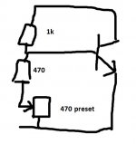
So it looks like this. Reducing the 470 ohm allows the BD139 to turn OFF more and so increase the bias volts which in turn allows more bias current to flow.
Be sure to turn the preset to the full 470 ohms first before powering up. That give the minimum bias possible.
Be sure to turn the preset to the full 470 ohms first before powering up. That give the minimum bias possible.
Attachments
After replacing the R620 with a 370 Ohms resistor I realized that I could have gone with a 330 one ( no 390 ohms in my parts bin) is up and running with 10mV across the emitter resistor for now.
Now the big question what is the ideal idle current for this type of amp ?
The A5 with the SAP15 darlington transistors ask for 13mV across the emittor resistor for an idle current of 70mA but that amp is a different animal.
Any ideas ?
Now the big question what is the ideal idle current for this type of amp ?
The A5 with the SAP15 darlington transistors ask for 13mV across the emittor resistor for an idle current of 70mA but that amp is a different animal.
Any ideas ?
What is the theoretical optimum and what the manufacturer recommends could be very different because of the heatsinks being to small in order to keep costs down.
The optimum value would be around 100 milliamps but if you find the amp runs to hot with that then you must go lower.
100ma would be 22 millivolts across each of the 0.22 ohm (and no speaker attached while setting because any DC offset skews the results as the load draws current)
The optimum value would be around 100 milliamps but if you find the amp runs to hot with that then you must go lower.
100ma would be 22 millivolts across each of the 0.22 ohm (and no speaker attached while setting because any DC offset skews the results as the load draws current)
Have set it up with 10mV with the bulb tester on and after removal it settled just bellow 13mV so +/-70mA.
Going to leave it like that for now and listen to a bit of music to see how he behaves heat wise.
Many thank Mooly for your help.
Going to leave it like that for now and listen to a bit of music to see how he behaves heat wise.
Many thank Mooly for your help.
 and you're very welcome. It got there in the end
 Just to say that I'm going to turn up the idle current to 15mV because there is still hardly any heat on the heatsinks (even touching the transistors directly).
Next job is to bring the A3i from the dead.
Thanks again
Next job is to bring the A3i from the dead.
Thanks again
Wait I'm going to the shop and get me a laser temps measuring device...
Just joking but I thought about that but for now I use my finger tips and there is hardly any heat, there is something but not the usual temp for an amp working for 4 hour strait.
My Cambridge Audio A5 with 13mV ( service manual) warms up very nicely this A1 is nothing in comparison
Just joking but I thought about that but for now I use my finger tips and there is hardly any heat, there is something but not the usual temp for an amp working for 4 hour strait.
My Cambridge Audio A5 with 13mV ( service manual) warms up very nicely this A1 is nothing in comparison
Last edited:
If the amp is delivering music OK for 4 hours and running cool then all it means is the heatsinks are more than adequate. The power dissipation has to be occurring (laws of physics Jim 😉).
So it looks like this. Reducing the 470 ohm allows the BD139 to turn OFF more and so increase the bias volts which in turn allows more bias current to flow.
Be sure to turn the preset to the full 470 ohms first before powering up. That give the minimum bias possible.
Not always wanting to correct but it is good practice to connect the wiper to the other now unused contact of the potentiometer. A bad wiper contact then has less impact.
I know, cause and effect.
It just doesn't feel right an working amplifier that doesn't heat up...
On the other hand I need to do something or else this depression takes the better over me.
To Jean-paul, but it works I now have more range on the trim pot.
It just doesn't feel right an working amplifier that doesn't heat up...
On the other hand I need to do something or else this depression takes the better over me.
To Jean-paul, but it works I now have more range on the trim pot.
Last edited:
Not always wanting to correct but it is good practice to connect the wiper to the other now unused contact of the potentiometer. A bad wiper contact then has less impact.
I'd never actually thought of it in those terms although I've seen what you suggest done often enough.
RS232 if the wiper were bad and the preset went open circuit then in your configuration the bias would default to the minimum (so amplifier safe).
This was the bit that didn't seem right when I was taking a while to unravel the pictures yesterday... and then you posted the transistor was mounted with the face side to the heatsink... so then it all made it sense configuration wise.
Also remember with the bias setting that ambient room temperatures are possibly lower than you might see in summer months and that alone can make a seemingly cool amplifier now appear to run quite warm later on.
Room temperature wise I understand where you going but it doesn't chance much we are in the UK after all and summer over here are not that hot.
I have other amplifiers and this one is the only one that doesn't heat up hence why I'm playing with it all the other ones (Cambridge A5 and A500, A3i (died recently) Marantz 7200, Cervin Vega and a few others) they all warm up nicely after 30 minutes to 1 hour of music and I'm not talking about my Class A amplifiers.
I have other amplifiers and this one is the only one that doesn't heat up hence why I'm playing with it all the other ones (Cambridge A5 and A500, A3i (died recently) Marantz 7200, Cervin Vega and a few others) they all warm up nicely after 30 minutes to 1 hour of music and I'm not talking about my Class A amplifiers.
All I can say is that is certainly isn't a problem.
If its playing music and delivering the load current then the dissipation is happening, and if its not getting warm then it is simply because all the metal work is getting rid of that heat.
As I mentioned earlier, the theoretical bias figure would actually be just over 100 milliamps for that output stage.
Would that make a difference?
Lets assume 30 volts (I don't know what the rails are in that amp) and compare 30 milliamps, 70 milliamps and 110 milliamps.
We get 0.9W, 2.1W and 3.3W respectively per transistor. Multiply that by four for the four transistors and you can see how it all adds up and makes quite a difference.
So up to you if you want to go higher 🙂
post 164
70mA? 13mV/0,22ohm = 59mA;
i guess you have measured the four 0,22 ohms res with your DMM or sowhat ?
have you compared the size ("weight") of the heatsinks in your A1 with the ones in your other amps ?
70mA? 13mV/0,22ohm = 59mA;
i guess you have measured the four 0,22 ohms res with your DMM or sowhat ?
have you compared the size ("weight") of the heatsinks in your A1 with the ones in your other amps ?
I'm happy with it and I'm going to give it a rest for now is playing sweet music and sounding great (not bad for a sub £40 amp).
The power supply is 2x24Vac so around +/-32Vdc
To mjf. sorry my mistake I tuck the number from the A5 service manual and had to reason to doubt it and didn't do the math (the A5 S/M states 13mV for 70mA idle current) is working fine with 16.5mV (75mA) and worming up nicely.
Case closed and thanks to everybody I'm moving on the next one (CA A3i).
Last edited:
TIP2955 and TIP3055 are quite generic transistors and should be available pretty much anywhere. I believe the original amp was designed with TIP35C and TIP36C. Either should work.
The TIP35/36 are capable of a bit more power so i'd probably use those. CPC order code SC06791 and SC06792
The Japanese devices are even better, but may cause issues in the circuit without alteration.. i would not advise using them without the schematic to assess
The TIP35/36 are capable of a bit more power so i'd probably use those. CPC order code SC06791 and SC06792
The Japanese devices are even better, but may cause issues in the circuit without alteration.. i would not advise using them without the schematic to assess
Had to reduce idle current to 15mV to be on the safe side not because it was to hot but because the heatsinks are small and I want it to be reliable.
Got my hands on a mint condition A1 mk1 with a preamp fault so had to buy it.
Long story short it works fine in "Direct" mode but right channel does down in "Normal" operation so have my work cut for tomorrow.
Because this amplifier is completely original (with original paper manual) and working condition I had to measure the idle current on the TIP3055/2955 that comes up to 0,4mV (2.2mA) across the 0.22 ohms resistors (checked with 3 different voltmeters).
How about that ?
In both channels? 0.4 mV across either resistor is only 1.8 mA bias current and seems like a useless amount, even if the design is CFP topology. If it was in that cindition when you received it, I'd say it was due to tinkering with the adjustment by a previous owner, a stabilising problem because the case is open or due to an original circuit fault that throttles the bias to that low level. No wonder it runs so cool and those tiny heatsinks work well enough. How about a bit of circuit tracing or "reverse engineering" of the output stage and post up a sketch?
A minimum bias current could be as low as 5mA for a Sziklai pair (CFP) or 30mA for an emitter follower (EF) and still sound acceptable. Given the design brief, I would have thought a conservative (EF) approach might have been in order but the comment earlier about cold heatsinks says otherwise.
A minimum bias current could be as low as 5mA for a Sziklai pair (CFP) or 30mA for an emitter follower (EF) and still sound acceptable. Given the design brief, I would have thought a conservative (EF) approach might have been in order but the comment earlier about cold heatsinks says otherwise.
- Home
- Amplifiers
- Solid State
- Cambridge audio a1 mk1 not powering on.