It is a bit unclear where you are measuring but something strange seems to be going on in power supply chain.here's the negative terminal of...
Can you take two more scope measurements (in ok and failure cases):
a) collector pins of Q16 (one channel) and Q32 (the other channel) - these should get +/-45V "immediately" after powerup;
b) junction of R37/R39 (one channel) and R47/R76 (the other channel)?
We need to be sure that the regulated voltage is ok in the failing scenario.
Sure:
a) collector pins of Q16 (one channel) and Q32 (the other channel) - these should get +/-45V "immediately" after powerup
Can't easily get into those pins but following the schematics I've hooked in these locations on D19 + D20:

Good power on / bad power on:
b) junction of R37/R39 (one channel) and R47/R76 (the other channel)?
a) collector pins of Q16 (one channel) and Q32 (the other channel) - these should get +/-45V "immediately" after powerup
Can't easily get into those pins but following the schematics I've hooked in these locations on D19 + D20:


Good power on / bad power on:


b) junction of R37/R39 (one channel) and R47/R76 (the other channel)?


Well, seems that +/-45V is just not present on the board in failure mode.
You could double check it with DMM.
You could double check it with DMM.
So to be clear: you think the power isn't making it from the mains board to the amp stage? As opposed to: the protection circuit is cutting power (because the two seconds haven't passed yet)?
I know I hear when the relays click on and off, and they don't click off before the two seconds have passed. (But I am still deeply suspicious of this relay, since it's been more obviously acting up these last few days.)
I know I hear when the relays click on and off, and they don't click off before the two seconds have passed. (But I am still deeply suspicious of this relay, since it's been more obviously acting up these last few days.)
Protection circuit is engaging the speaker protection relay, it should not turn off the power - or does it?So to be clear: you think the power isn't making it from the mains board to the amp stage? As opposed to: the protection circuit is cutting power (because the two seconds haven't passed yet)?
Anyhow, yes, you seem to be lacking power on the board.
I understand from the schematics that 540A is powered from only one secondary winding (that would explain why both power rails fail symmetrically) - if so then the powerup relay may be the suspect (the one that was problematic some postings ago).
Or cabling or soldering problems somewhere.
Last edited:
One more suspect I found - it seems that plugging in earphones deactivates the speakers in this amplifier?
The schematic is presented "in bits and pieces" but it seems that the power relay may be disengaged also by dirty contacts in the headphones socket:

These contacts may get little use and develop quite some oxide on their surfaces.

Worth spending a moment and measuring their resistance with DMM.
Quick and fast remedy would be some dry contact cleaner and pushing/pulling a headphone plug in and out from the socket for some tens of time.
Could explain the clicking on and off that you wrote about some posts ago.
The schematic is presented "in bits and pieces" but it seems that the power relay may be disengaged also by dirty contacts in the headphones socket:
These contacts may get little use and develop quite some oxide on their surfaces.
Worth spending a moment and measuring their resistance with DMM.
Quick and fast remedy would be some dry contact cleaner and pushing/pulling a headphone plug in and out from the socket for some tens of time.
Could explain the clicking on and off that you wrote about some posts ago.
Last edited:
I took a moment to measure voltage (AC) at J13 and J14 on the amp stage: these are fat wires that are soldered in straight from where they leave the mains PCB. On a good power up, they sit at 35V or so, per my multimeter, and on a bad power up they bounce but both settle quickly back to zero.Protection circuit is engaging the speaker protection relay, it should not turn off the power - or does it?
Anyhow, yes, you seem to be lacking power on the board.
I understand from the schematics that 540A is powered from only one secondary winding (that would explain why both power rails fail symmetrically) - if so then the powerup relay may be the suspect (the one that was problematic some postings ago).
Or cabling or soldering problems somewhere.
J18 and J19 on the little mains PCB stick at 35V though.
Interesting; I'll take a look.One more suspect I found - it seems that plugging in earphones deactivates the speakers in this amplifier?
The schematic is presented "in bits and pieces" but it seems that the power relay may be disengaged also by dirty contacts in the headphones socket:
These contacts may get little use and develop quite some oxide on their surfaces.
Worth spending a moment and measuring their resistance with DMM.
Quick and fast remedy would be some dry contact cleaner and pushing/pulling a headphone plug in and out from the socket for some tens of time.
Could explain the clicking on and off that you wrote about some posts ago.
If I recall correctly: engaging the headphone socket doesn't change the protection behavior. But I'll poke around to make sure.
So you start tracking the wires, good old detective work ... 😉...on a bad power up they bounce but both settle quickly back to zero.
J18 and J19 on the little mains PCB stick at 35V though.
That may be if the contact of the switch is too bad for the circuit it is driving.engaging the headphone socket doesn't change the protection behavior.
These fat wires should (there seems to be typos in the numbering of terminals J3/J13 and J4/J14 in the schematics) "come" to mains PCB from power transformer secondary winding via the power relay.these are fat wires that are soldered in straight from where they leave the mains PCB. On a good power up, they sit at 35V or so, per my multimeter, and on a bad power up they bounce but both settle quickly back to zero.
35V on them is AC
which corresponds to ca 49V DC when rectified and smoothed which is to be expected.
If these wires settle to zero then you have the "culprit" - power relay or its driving circuit which cannot engage it occasionally.
And the relay driver circuit seems to include the contacts in the headphone socket...
Last edited:
There is no RL1 on the 540A; RL1 is present only on the 640A.These fat wires should (there seems to be typos in the numbering of terminals [...]
View attachment 1265731
RL2 connects to J18/J19 to J20/J21 on the mains PCB. J20/21 are connected to J13/J14 on the amp stage.
Will take a look at the headphone part soon, too.
While I'm not looking at the unit itself, I've been trying to decipher relay specs to buy a suitable replacement. RL2 is:
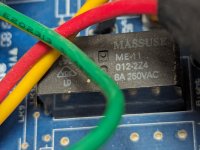
MASSUSE ME-11 012-2Z4 8A 250VAC
The Massuse spec sheet takes a little deciphering: http://www.massuse-relay.com/details/ME-11.pdf
The Cambridge Audio spec sheet describes it as "8A-250VAC 2P2T"
Filtering on mouser gets me close, I think. TE Connectivity RT424A12 looks close but the spec sheet shows a form factor with an extra pin.
Certainly connecting the headphones disengages the speaker output relays. Occasionally on power-on it takes a tenth of a second to spot the headphones and disengage the speaker outputs.One more suspect I found - it seems that plugging in earphones deactivates the speakers in this amplifier?
The schematic is presented "in bits and pieces" but it seems that the power relay may be disengaged also by dirty contacts in the headphones socket:
View attachment 1265535
Worth spending a moment and measuring their resistance with DMM.
Quick and fast remedy would be some dry contact cleaner and pushing/pulling a headphone plug in and out from the socket for some tens of time.
Could explain the clicking on and off that you wrote about some posts ago.
Using the headphones doesn't change the DC protection behavior. The protection either fires when coming out of standby or it doesn't. The only difference is that if the headphones are engaged, then there isn't the click of the output relays turning on/off when the protection fires.
Resistance measurements: I read 11.9 ohm across the R channel + R11, and 11.9 ohm across L channel + R12. (Cable resistance is 1.9 ohm.) Measuring the ground pin on the cable through to the chassis/mains earth reads 50 ohms or so; that seems high?
CN2 runs up to the little front panel PCB. I'm not gonna mess with that stuff.
Sorry, cannot understand the measuring points.I read 11.9 ohm across the R channel + R11, and 11.9 ohm across L channel + R12. (Cable resistance is 1.9 ohm.)
There seems to be a 50R ground lift between chassis and amplifier ground - you should measure against rectifier ground.Measuring the ground pin on the cable through to the chassis/mains earth reads 50 ohms or so; that seems high?
Ah ok; I think I follow. I measured ground on the headphone socket against another ground point labeled MAINS, like in the headphone schematic, and the multimeter measures ~0.1 ohm to it.
For the left and right channels on the headphone socket: I measured through the resistors labelled R11 and R12 in the image you pasted for no better reason than I was tired. But the cable measures 1.9 ohm and the resistors are 10 ohm each, so these readings are fine.
In other words, this seems fine. Was that what you were initially asking?
Either way:
This is the part I'd like help with.While I'm not looking at the unit itself, I've been trying to decipher relay specs to buy a suitable replacement. RL2 is:
View attachment 1266103
MASSUSE ME-11 012-2Z4 8A 250VAC
The Massuse spec sheet takes a little deciphering: http://www.massuse-relay.com/details/ME-11.pdf
The Cambridge Audio spec sheet describes it as "8A-250VAC 2P2T"
Filtering on mouser gets me close, I think. TE Connectivity RT424A12 looks close but the spec sheet shows a form factor with an extra pin.
Doing a search for the MASSUSE replacement, I found this thread on Audiokarma: https://audiokarma.org/forums/index.php?threads/massuse-me-11-relay-replacement.623939/. Mouser stocks these (Altech RM84-2012-35-1012). I just glanced at the specs and they seem correct but I would check them against the MASSUSE datasheet.
Nope, I was asking to measure resistance of the contact pair that is connected to the two CN2 wires.Was that what you were initially asking?
But taking a step back - the power relay seems to perform ok when started from "cold" i.e. from unpowered state.
But it fails to connect properly when started from standby.
Possible causes that I can think of:
a) in standby the relay driver transistor is not fully closed so the "start" for the relay is not from the initial position but from some intermediate state.
You could measure DC over the relay coil in standby mode - I would expect it to be zero.
b) the relay driver transistor is not opening fast enough when coming out from standby - so the mechanical acceleration of relay contacts is less than from "cold start".
You could put a scope probe on each of the relay coil leads and test (in DC mode) both success and failure scenarios.
Nope, I was asking to measure resistance of the contact pair that is connected to the two CN2 wires.
Then I have no idea how to parse that part of the schematic! I'll take a look another day.
For reference I'm sticking probes on the ends of D11, based on the schematics, to measure across the coil end of the relay:You could measure DC over the relay coil in standby mode - I would expect it to be zero.
...
You could put a scope probe on each of the relay coil leads and test (in DC mode) both success and failure scenarios.
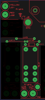
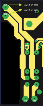
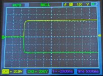
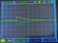
Here are the success and failure cases:
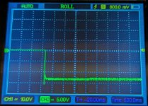
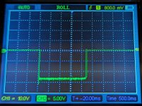
That ~13V or so arrives immediately when I press the standby button. In the failure case: it stays there until the 2 seconds startup have passed and the protection circuit kicks in.
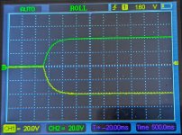
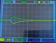
I realized I didn't post images of what happens to the AC in/out of the relay on the way to the amp. I've grabbed a few shots of those (in AC mode). I showed the stage prior to the relay, but it's always on and doesn't budge.
Those paths are:
J18 -> relay -> J20 -> red wire -> J13 on amp stage
successful start:
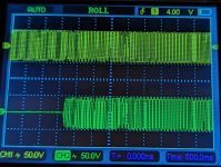
successful power-off, and a successful power-off with trailing voltage (?):
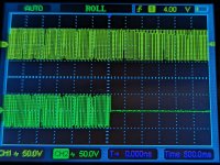
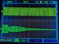
failure cases: the blip is where I press the standby button. The second has a weird echo.
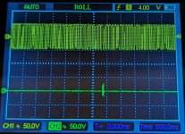
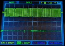
I get similar on the other pathway through the relay:
J19 -> relay -> J21 -> yellow wire -> J14 on amp stage
Successful startup:
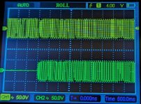
successful power-off, and a successful power-off with trailing voltage (?):
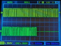
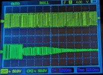
failure case: again, the blip is where I press standby.
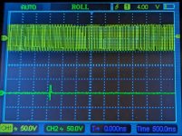
So in these failure cases, there's a tiny blip of voltage but, very little activity, and no activity when the protection fires.
When I poked the same points with my DMM previously, it seemed like the VAC was more apparent in this case, rising then trailing off comfortably within the two second wakeup window. But that doesn't seem so apparent now, with the scope.
On which end of the diode has that been measured - there is just one channel on the screenshot?That ~13V or so arrives immediately when I press the standby button.
- Home
- Amplifiers
- Solid State
- Cambridge Audio 540A protection circuit engaging: troubleshooting