Okay, fair points all. It's probably good to get those parts replaced. Similar to the R57 noted above; I ought to be able to replace that too. I'll have to buy parts for each of these (I don't have any capacitors in that style here, and I figure the type of capacitor is important.)
I'm aware also that the glue cruft is on the pre-amp board, and not the amp board that's probably triggering the protection circuit. Fair to tidy up easy things, but I wonder if they're the culprit. Guess I'll find out!
Also, I do have a cheap scope. I'll see if I can drive it to get anything useful out of it.
Digital. I've mostly used it for trigger conditions when debugging old computers. Not sure how long of a history window it holds.
Probably you need ca 10 seconds of signal on screen (as a start) and then you should save the waveform.Not sure how long of a history window it holds.
If the scope cannot save the screenshot into file then next way would be to take a photo of it with your phone or camera.
The screenshot in my post some posts above is from Picoscope which has served me well for many years.
I've run into protection circuits that use a thyristor to latch a correct voltage, but too high a voltage will drive a mosfet gate, causing it to conduct, and trigger a power error.
Diodes are the first place I would look. The full wave rectifier is probably good. But smaller, possibly glass diodes, can fail so they don't block. Then you get current running who knows where.
Failed comparators and regulators, and voltage dividers out of tolerance can produce too low a voltage to drive a bipolar base, which can cause a comparator to remain unset. When the circuit checks the comparator, and it's not set, it raises the voltage input, and fails to drop it again.
Op amp voltage dividers can drift out of spec, or fail, causing the output to be way off, and also failure to decrease impedance if that is the purpose of the op amp.
A thyristor is like a transistor, but it continues to conduct (latches) with no signal to the gate. To turn one off, the current passing through it must be dropped below a certain level, depending on the thyristor. They are commonly used in power circuits, in solid state relays, to signal error conditions involving very weak signals--the gate needs only millivolts to latch the current flow, and the amount of current has a wide range.
Most power circuits use at least one thyristor, and they frequently fail.
I would test each resistor in circuit, and make sure each gives some reasonable value. Test every diode both ways.
Testing a thyristor.
From the top, left to right, thyristor leads are cathode, gate, anode. To test one, put your DMM on resistance. Measure a general purpose PN diode. If it doesn't conduct, the negative lead is connected to the anode.
On the thyristor, connect the positive ohmmeter lead to the anode, and the negative lead to the cathode. There should be no continuity. Move the negative ohmmeter lead from the cathode to the gate, and keep the positive lead on the anode. There should be continuity. If the thyristor has continuity before touching the gate, it's shorted. Is no continuity after the gate is touched, it's open.
Last edited:
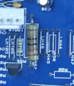
On a more fundamental note: R57 is listed in the spec as "220R 2W Carbon". I'll stick to the same spec, I just don't know the difference between types of resistors, or why this one is this particular type. Mouser exposes a ton of options, and I'm paralyzed by choice 😅
Attachments
Khm, 38 results is not nearly "ton..." 😉Mouser exposes a ton of options,
From that list I would take the metal film Vishays but I really do not think it does matter (in this power rail application) as long as it is a new one.
Last edited:
I clearly didn't filter strongly enough. Anyway, it's a lot of info as somebody who's not up to speed on the materials that go into resistors 😀
Parts inbound from mouser. My cheap scope is a handheld hantek and I just can't for the life of me drive the desktop software to give me a useful trace. So it'll be photos from the device screen itself.
I'm going to try to grab some readings for a good power-on/power-off, and a bad power-of/fault trip before I pull anything off the board. I'll pull off the old components, clean everything up, and drop in new components then test again. I'm hopeful that baselining to clean connections and fresh components gets me a more stable system.
I would advise against such policy 😉I'll pull off the old components, clean everything up, and drop in new components then test again.
If you can get your scope to record the startup phase then there are 3 places to investigate:
a) the output voltage (terminal 16 on schematics);
b) regulated voltage rails (R76 and R37 on the posted schematics, the ends "off from the regulating transistor");
c) bias voltages on driver transistor bases.
Once you get these recorded in both success and failure scenarios then some guesses can be made for proceeding.
Okay, here goes; I think I got the correct things!
a) J16 was consistently 0V relative to ground. I measured J12 instead because it was active:
Left: good power-on from standby
Right: entering standby from that good power-on:


And J12 when protection is triggered coming out of standby. The unit always takes ~2 seconds to come out of standby, and the protection circuit usually triggers immediately when those ~2 seconds are over. The circuit triggers just after the up/down spike here:

b) regulated voltage rails
R37:
Left: good power-on from standby
Right: entering standby from that good power-on (the long-tail on the right dips to meet 0V after another 1-2 seconds)


R37 when the protection is triggered coming out of standby:

R76 good power-on, good standby:


R76 bad:

c) bias voltages on driver transistor bases
Little bit of inference here on my part, but I assume you mean the 'middle' pin on the schematic and it was easiest for me to measure from R61 and R73).
R61: Good power-on, good standby:


R61 bad:

R73, good power-on, good standby:


R73, bad:

a) J16 was consistently 0V relative to ground. I measured J12 instead because it was active:
Left: good power-on from standby
Right: entering standby from that good power-on:
And J12 when protection is triggered coming out of standby. The unit always takes ~2 seconds to come out of standby, and the protection circuit usually triggers immediately when those ~2 seconds are over. The circuit triggers just after the up/down spike here:
b) regulated voltage rails
R37:
Left: good power-on from standby
Right: entering standby from that good power-on (the long-tail on the right dips to meet 0V after another 1-2 seconds)
R37 when the protection is triggered coming out of standby:
R76 good power-on, good standby:
R76 bad:
c) bias voltages on driver transistor bases
Little bit of inference here on my part, but I assume you mean the 'middle' pin on the schematic and it was easiest for me to measure from R61 and R73).
R61: Good power-on, good standby:
R61 bad:
R73, good power-on, good standby:
R73, bad:
DC mode should it be in this case 😉
And remember to shunt the probes 1:10 (as safety precaution - I do not know the max input voltage of your scope).
And remember to shunt the probes 1:10 (as safety precaution - I do not know the max input voltage of your scope).

2C42, I think. Cheap as chips, I needed it in the past to debug some clocks and data lines in old computers. But the software is janky and the open solutions don't support that model line.
I know where to set it to DC though. Just takes a little stabbing around to find again.
I know where to set it to DC though. Just takes a little stabbing around to find again.
User manual is easy to find in the net, instructions are there 😉Just takes a little stabbing around to find again.
yeah I know how to use it, but, it's a handheld and settings are buried in 2-3 layers of options menus that sometimes have 5 or 6 pages each. AC or DC is a few steps away from the top so I didn't think about it yesterday 😅
Be sure to x10 probes to minimize load capacitance, especially when probing inter-stage test points. Shunt capacitance to ground can provoke oscillation. Have seen it many times...
I have seen recommendations to use 1k resistor in series with the probe in some amplifier service manual.Shunt capacitance to ground can provoke oscillation.
- Home
- Amplifiers
- Solid State
- Cambridge Audio 540A protection circuit engaging: troubleshooting