Sweet! Does this look reasonable to you?Doing a search for the MASSUSE replacement, I found this thread on Audiokarma: https://audiokarma.org/forums/index.php?threads/massuse-me-11-relay-replacement.623939/. Mouser stocks these (Altech RM84-2012-35-1012). I just glanced at the specs and they seem correct but I would check them against the MASSUSE datasheet.
Pars: "I would check them against the MASSUSE datasheet." - three things you need to check - coil voltage, contacts current and pinout (so it would fit on your board). Manufacturer - providing you resort to known brands - is not that important for me personally.
Then, as I read these sheets, this should be good. Leg spacing is 7.5mm across on the Altech vs 7.62mm on the MASSUSE but every pinout I've looked at so far is also 7.5mm, and I figure there's tolerance here.
I'll aim to replace the relay, then see if that fixes things or if there's anything else triggering this fault. If that's looking good, I'll probably look at some housekeeping while the unit is open: replacing the carbon resistor you pointed at very early in the thread, and probably also the diodes/capacitors that were sitting under dried glue for 15 or so years. I think I have replacements for all those and they should be easy.
I'll aim to replace the relay, then see if that fixes things or if there's anything else triggering this fault. If that's looking good, I'll probably look at some housekeeping while the unit is open: replacing the carbon resistor you pointed at very early in the thread, and probably also the diodes/capacitors that were sitting under dried glue for 15 or so years. I think I have replacements for all those and they should be easy.
Good, we can continue from there.I'll aim to replace the relay, then see if that fixes things
Khm, I think I do not deserve this honour, IIRC I just agreed to it showing signs of overheating......replacing the carbon resistor you pointed at very early in the thread,
To be honest, I have never replaced such components unless the resoldered joint did not look unsatisfactory.and probably also the diodes/capacitors that were sitting under dried glue for 15 or so years.
But these components are cheap, so if it makes you feel better then it is definitely worth doing.
Oh, yes, misremembered by me!
Editing to add: also, yeah, I don't usually go aggressively on needlessly replacing components. The carbon resistor(s) seem like good things to replace though. Maybe the capacitors just as a refresh and since I have replacements.
Editing to add: also, yeah, I don't usually go aggressively on needlessly replacing components. The carbon resistor(s) seem like good things to replace though. Maybe the capacitors just as a refresh and since I have replacements.
Last edited:
If you want to be adventurous then (on one channel as a test) you could jump the input buffer with a wima film cap:Maybe the capacitors just as a refresh and since I have replacements.
Opamps as input buffers driving the next chip some centimeters away are just sound killers for me.
Can you describe more, or give pointers?If you want to be adventurous then (on one channel as a test) you could jump the input buffer with a wima film cap
If the amp is still misbehaving, then maybe I'll buy a replacement "main" amp and this one becomes my "project" amp. And then I'm much more willing to experiment 😀
Solder out the input lytic capacitor and opamp straight after the RCA socket on some input channel.Can you describe more, or give pointers?
Then solder a film capacitor from RCA socket center connector to the input selector switch. Ca 100k from RCA socket center connector to ground will not hurt either. 100pF from incoming signal to ground - depends on your ears, I usually solder them out.

Yeah, the size difference might be a problem, although a user on audiokarma claimed that he replaced the MASSUSE relay on his with the Altech (think his was a 640 though). 7.62mm does seem to be fairly common as well, but I wasn't able to find a suitable replacement relay (but did not look exhaustively). I was looking at some Omron relays as I use that brand quite a bit. The ones I found were too low of current though. It seems that the MASSUSE part can be found on aliexpress, but who knows what that may be. MASSUSE seems to not be a manufacturer, but a distributor of some type.Then, as I read these sheets, this should be good. Leg spacing is 7.5mm across on the Altech vs 7.62mm on the MASSUSE but every pinout I've looked at so far is also 7.5mm, and I figure there's tolerance here.
You can always build a raiser board...
Mouser selection for 12V 8A relay:
https://www.mouser.ee/c/?q=12v relay dpdt 8A&instock=y
Mouser selection for 12V 8A relay:
https://www.mouser.ee/c/?q=12v relay dpdt 8A&instock=y
Eh, well, I figured a difference of 0.12mm wasn't gonna be a problem, and in reality the pin layout is basically identical. Perhaps MASSUSE measure from the outside of the pins rather than within the pins?
Either way, an unambiguously easy fit:

The DC protection fault hasn't kicked in so far, so I'm pretty confident. I'll give this a day or two before anything doing else.
So, more to follow with anything else we spotted while I've been in here like those old carbon resistors. Also I noticed at some point that the pre-amp board was still running while it should have been in standby, but its power doesn't go via this relay. Will see if that's still the case.
Editing to add: actually it feels like the pre-amp is shutting off now (the heatsink cools down!)
Either way, an unambiguously easy fit:
The DC protection fault hasn't kicked in so far, so I'm pretty confident. I'll give this a day or two before anything doing else.
So, more to follow with anything else we spotted while I've been in here like those old carbon resistors. Also I noticed at some point that the pre-amp board was still running while it should have been in standby, but its power doesn't go via this relay. Will see if that's still the case.
Editing to add: actually it feels like the pre-amp is shutting off now (the heatsink cools down!)
Last edited:
That may be a result of inch to metric conversion in datasheets.figured a difference of 0.12mm wasn't gonna be a problem,
It's not too difficult to find replacement transistors. It's just that no one wants to really look. They just want a web page that tells them. You just need to know what the part does in its role in a piece of equipment, find the specs for the old part, and do a parametric search on digikey or mouser. Those are about the only 2 that actually work.Besides, has anyone looked into a replacement alternative? (just for my personal culture)
It's been a long time since I kicked this generation of amps off my shelves but if a friend asks me to repair one in a few years, it's always good to have a plan B
When you find something similar, buy it some place cheap. I needed a replacement triac to control the fuser in a 30-y.o. printer, and I found one. I bought 50, and sold them for 5x what I paid. Quite a few people were looking for that part. The way it was heat-sinked, it was a design feature of planned failure.
So it's been five days and the unit has been behaving; the DC protection fault hasn't triggered once. The amp is very happy to come out of standby now. I'm extremely happy with this fix.
One thing that I'm wondering about: I noticed that when the unit is in standby, the heatsink attached to the three voltage regulators on the pre-amp stage is usually pretty warm. It might be that it's always been warm and I've never noticed with the case closed, but I'm curious about it.
The section in question:

CN8 comes straight from the mains board and it isn't gated by the relay I just replaced, so I figure it makes sense that these are running and generating a little heat at all times. They're not outrageously hot, but the heatsink is definitely fairly warm.
Of course the unit needs to be running +5V for the IR receiver, panel buttons, etc, to operate at all, and that comes from U3 above.
"Unreg for relays" is fed back to the mains PCB and is used on the relay I just replaced. And since that line is always active, it makes sense that there's voltage on the input into U4 in the diagram.
Given those two, I figure the input on U2 is always active, too.
So, my question is: is it typical for these voltage regulators to be generating heat while in standby? I've had this thing for a long time and I've never noticed it. This feels like a "stupid" question, I'm just genuinely curious if this is typical or if something is drawing current that should actually be off.
One thing that I'm wondering about: I noticed that when the unit is in standby, the heatsink attached to the three voltage regulators on the pre-amp stage is usually pretty warm. It might be that it's always been warm and I've never noticed with the case closed, but I'm curious about it.
The section in question:
CN8 comes straight from the mains board and it isn't gated by the relay I just replaced, so I figure it makes sense that these are running and generating a little heat at all times. They're not outrageously hot, but the heatsink is definitely fairly warm.
Of course the unit needs to be running +5V for the IR receiver, panel buttons, etc, to operate at all, and that comes from U3 above.
"Unreg for relays" is fed back to the mains PCB and is used on the relay I just replaced. And since that line is always active, it makes sense that there's voltage on the input into U4 in the diagram.
Given those two, I figure the input on U2 is always active, too.
So, my question is: is it typical for these voltage regulators to be generating heat while in standby? I've had this thing for a long time and I've never noticed it. This feels like a "stupid" question, I'm just genuinely curious if this is typical or if something is drawing current that should actually be off.
The 15V regs are powered the same way as the +5V, so they seem to be ON in standby.when the unit is in standby, the heatsink attached to the three voltage regulators on the pre-amp stage is usually pretty warm.
Search the service manual for +15V and you will find plenty of opamps being powered by +/-15V rails when in standby.
Why did they do it that way - because they could?
Yeah, fair; thanks for the sanity check. Mainly I wasn't sure if I was missing something on the schematic, but it sounds like no.
I put the thing through a cheap energy meter, and it looks like it draws marginally more than 10W while on standby and ~26W while active with no actual input. The service manual says standby is "<10W" and active is "<30W", so that's about right.
I went back to the caps/diodes with the crufty glue and switched those out.


All parts replaced during this work:

I've buttoned the amp up and I'm declaring a victory.
Thanks for your help as I learned my way around this. Super happy with the fix!
I put the thing through a cheap energy meter, and it looks like it draws marginally more than 10W while on standby and ~26W while active with no actual input. The service manual says standby is "<10W" and active is "<30W", so that's about right.
I went back to the caps/diodes with the crufty glue and switched those out.
All parts replaced during this work:
I've buttoned the amp up and I'm declaring a victory.
Thanks for your help as I learned my way around this. Super happy with the fix!
Hello
I saw that you work on amplifier cambridge 540a v2.
I need your help, I am not a specialist of electronic.
I have an amplifier cambridge 540a v2 and to upgrade this amplifier, I install inside a dac.
For that I need space and I remove and disconnect the Board Abus Module (AP17708/4).
Now the remote control don't work.
Do you have a solution , to fix this problem and keep the Board Abus Module removed.
Let me know
Best regards
Attachments
Hello again,
To be clear, the Board Abus Module is necessary only for a very special use (Not necessary for my use).
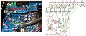
I disconnect the 2 connectors CN09 and CN10 of the Input PCB Board (AP17649/4)
Il is perhaps possible to by-pass this abus Functions.
How, i don't know..................
Let me know
Best regards
To be clear, the Board Abus Module is necessary only for a very special use (Not necessary for my use).
I disconnect the 2 connectors CN09 and CN10 of the Input PCB Board (AP17649/4)
Il is perhaps possible to by-pass this abus Functions.
How, i don't know..................
Let me know
Best regards
- Home
- Amplifiers
- Solid State
- Cambridge Audio 540A protection circuit engaging: troubleshooting