hi folks; I have an old Cambridge Audio Azur 540A amplifier which I've had for 15 or so years, and which has in the last few weeks started firing a protection system error.
I've pulled the unit out, disconnected all inputs and outputs, and put it on its own mains outlet. When I turn the unit on by selecting an input, it's likely (50% of the time) to immediately click into an error state, with the red light blinking once for a DC detected on output error. This is true whether I have speaker B selected or not. This even happens if the headphone jack is interested, which might be important (as a totally different output path, though maybe the protection circuit checks them all anyway?). Once a channel is successfully selected, the amp almost never triggers an error; it's usually only when coming out of standby.
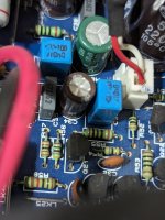
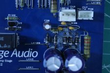
I popped the case and, referring to this post I measured DC across J6 and J12 and their adjacent negative lines, and the numbers seemed very small (but I'll likely probe more systematically).
i'm curious to hear folks experiences or thoughts on this before I go down the rabbit hole. This amp has some sentimental value so I'd like to get it working again rather than buying new; in the past I've had to replace the relays, but otherwise the unit has caused me no problems until now!
I've pulled the unit out, disconnected all inputs and outputs, and put it on its own mains outlet. When I turn the unit on by selecting an input, it's likely (50% of the time) to immediately click into an error state, with the red light blinking once for a DC detected on output error. This is true whether I have speaker B selected or not. This even happens if the headphone jack is interested, which might be important (as a totally different output path, though maybe the protection circuit checks them all anyway?). Once a channel is successfully selected, the amp almost never triggers an error; it's usually only when coming out of standby.
I popped the case and, referring to this post I measured DC across J6 and J12 and their adjacent negative lines, and the numbers seemed very small (but I'll likely probe more systematically).
i'm curious to hear folks experiences or thoughts on this before I go down the rabbit hole. This amp has some sentimental value so I'd like to get it working again rather than buying new; in the past I've had to replace the relays, but otherwise the unit has caused me no problems until now!
Measure between the junction of C42 & C43 and J12 for an accurate measurement. There should be less than 100mV DC. Any more and the protection will trip. The Headphone jack has its own amplifier.
If more or unstable, firstly check the Fb capacitors; C37 and C34 for leakage electrically.
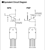
Those SAP*** output Darlingtons are no longer available so proceed with great care!
If more or unstable, firstly check the Fb capacitors; C37 and C34 for leakage electrically.
Those SAP*** output Darlingtons are no longer available so proceed with great care!
Besides, has anyone looked into a replacement alternative? (just for my personal culture)Those SAP*** output Darlingtons are no longer available so proceed with great care!
It's been a long time since I kicked this generation of amps off my shelves but if a friend asks me to repair one in a few years, it's always good to have a plan B
Measure between the junction of C42 & C43 and J12 for an accurate measurement. There should be less than 100mV DC. Any more and the protection will trip. The Headphone jack has its own amplifier.
If more or unstable, firstly check the Fb capacitors; C37 and C34 for leakage electrically.
Those SAP*** output Darlingtons are no longer available so proceed with great care!
Okay, looking at the schematic and following wires: I'm measuring from one of the pins on the other end of the little two-pin CN5 header (which seems to be connected to C42 and C43), and the exposed solder blob at the other end of the red wire that exits J12. If I'm reading from the wrong points, I'm all ears.
Good state, when the protection isn't triggered: when I switch the unit on from standby, the voltage jumps momentarily to anything from 5V to 30V, so far as my multimeter can show me, but settles down quickly to around 10mV. When I put the unit back in standby, the voltage jumps again (usually to 20-30V) briefly before dropping rapidly to around 0.4V.
Bad state, which does trigger the protection circuit: as before, the voltage jumps briefly, and it's dropping when the protection circuit kicks in. But it's still typically over 1V.
So the protection circuit is reading something bad and responding correctly.
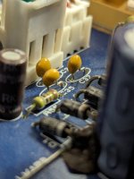
Visually, C37 looks fine. C34 I'm still hunting for (it's gotta be there, somewhere, but it's late and I haven't found it yet!)
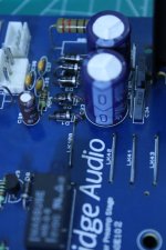
Relatedly, the bigger capacitor next to C32 is caked in brown gunk. Is this just some 15-20 year old glue?
Attachments
There are no "drop in" replacements.Besides, has anyone looked into a replacement alternative? (just for my personal culture)
It's been a long time since I kicked this generation of amps off my shelves but if a friend asks me to repair one in a few years, it's always good to have a plan B
Totally obsolete old technology. I suppose a standard Darlington ; (BD64/65 and fudge a couple of R22 resistors in the circuit).
Not for me. Original parts or no repair.
Attachments
Last edited:


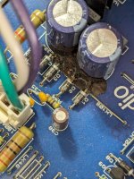
stripped away some of that dried up glue; the now-exposed legs on D1-5 look a little nasty. Will try to photo in good light at the weekend.To start, look under the glue, I see oxidation on the conductors.
And look also under the PCB too .
haven't gotten to the underside yet; is there a good document describing the best way in? Otherwise I can keep unscrewing things until I get there.
pretty well convinced by this point that C34 doesn't exist, also 😅
Cleaned up around that old glue. Those legs look a little dinged up but ... is that likely to be a problem?
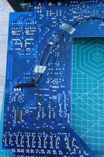
The underside of the board looks clean as a whistle. Top-side, too, actually.
What should I test here, though?
The underside of the board looks clean as a whistle. Top-side, too, actually.
Also I finally found C34 as suggested earlier, and it looks in good shape, too. Caps will dry out, but none of the caps on the board seem to have leaked or exploded.If more or unstable, firstly check the Fb capacitors; C37 and C34 for leakage electrically.
What should I test here, though?
Attachments
Looks pretty much like R56 on the photo - why do you judge it to have been overheated?She had a heat stroke.
Are we discussing this resistor?discolored in the center and the second red ring is almost gone
It would be best if you could trace and record the startup conditions in both success and failure states in various points (power stage output, power rails, input etc) with a digital oscilloscope.What should I test here, though?
Something in style:
The goal would be to find the behaviour differences during the period when the protection relay engagaes or goes into failure state.
I am afraid that catching such an intermittent error by just replacing components may be time consuming...
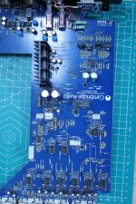
As one of the first things (does not need a scope) I would measure the rail voltages on the power amplifier board in both channels.
These should be equal between channels and same in both (success and failure) conditions.
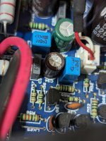
Since I got tired one day of poking around for 10 voltages (per measurment, risking shorting something during that activity and having to write down the values fast) then I bought 10 cheapest multimeters, soldered pins to the points of interest, connected the meters via hook cables and just took a photo in the moment I needed for documenting later:

Edit:
this photo was taken when I did not yet have a set of hooked cables - with crocodiles things get a bit cramped.
These should be equal between channels and same in both (success and failure) conditions.
Since I got tired one day of poking around for 10 voltages (per measurment, risking shorting something during that activity and having to write down the values fast) then I bought 10 cheapest multimeters, soldered pins to the points of interest, connected the meters via hook cables and just took a photo in the moment I needed for documenting later:
Edit:
this photo was taken when I did not yet have a set of hooked cables - with crocodiles things get a bit cramped.
That is not enough, you need to unsolder the capacitors C32/C33 and clean the dried up glue that has accumulated underneath. Use desoldering braid as a method of removing solder. Replace both capacitors with a new pair of the same or better characteristics (they are cheap as chips), and be careful about the orientation when installing the new ones. Clean the solder joints and around them with a few drops of isopropyl alcohol and an ear swab.Cleaned up around that old glue.
This is not a problem per se, but the corrosion that has accumulated on the diode leads precisely because of the corrosive effect of the glue is... unsolder all the diodes (again, use desolder braid) and replace all the diodes with new ones (they are cheap as chips), and be careful around orientation when installing new ones. Clean the solder joints and around them with a few drops of isopropyl alcohol and an ear swab.Those legs look a little dinged up but ... is that likely to be a problem?
- Home
- Amplifiers
- Solid State
- Cambridge Audio 540A protection circuit engaging: troubleshooting