Yes, I've done that. Sometimes I cut a resistor's leads very short, capture one end in the probe clip, and poke around with the exposed lead.
Okay, same sequence as before:
a) J12:
Left: good power-on from standby
Right: entering standby from that good power-on:


And J12 when protection is triggered coming out of standby:

b) regulated voltage rails
R37:
Left: good power-on from standby
Right: entering standby from that good power-on
(I've moved the zero baseline up in these, but the camera slipped so you can't see where that is on the y-axis here)


R37 when the protection is triggered coming out of standby:

R76 good power-on, good standby:


R76 bad:

c) bias voltages on driver transistor bases
Like last time, a little bit of inference here on my part: assuming the 'middle' pin on the schematic, I measured from R61 and R73 which were easier to reach.
R61: Good power-on, good standby:


R61 bad:

R73, good power-on, good standby:


R73, bad:

a) J12:
Left: good power-on from standby
Right: entering standby from that good power-on:
And J12 when protection is triggered coming out of standby:
b) regulated voltage rails
R37:
Left: good power-on from standby
Right: entering standby from that good power-on
(I've moved the zero baseline up in these, but the camera slipped so you can't see where that is on the y-axis here)
R37 when the protection is triggered coming out of standby:
R76 good power-on, good standby:
R76 bad:
c) bias voltages on driver transistor bases
Like last time, a little bit of inference here on my part: assuming the 'middle' pin on the schematic, I measured from R61 and R73 which were easier to reach.
R61: Good power-on, good standby:
R61 bad:
R73, good power-on, good standby:
R73, bad:
I bought the lowest variance version of the resistor mentioned earlier in this thread 🙂Friends don't let friends use carbon film resistors.
But I haven't modified anything on the board yet. I'd be quite happy to swap out those resistors, or pull the old caps/diodes, clean, and replace. But I'll hold for now, happy to not introduce fresh problems.

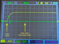
And J12 when protection is triggered coming out of standby:
The output of the amplifier does not return to zero so protection circuit may act correctly by not engaging the relay.
Regulated power measurements soom to have gone "a bit south" - what we would need to see (to be sure there are no problems with regulators) are the "left ends" of R37 and R76 compared to ground. With both voltages on the same screen so we can be sure that there are no timing differences during the startup (just to eliminate the obvious).
As bias voltage graph it would be good to see what is going on on the ends of C50 compared to ground. Again - both graphs in the same screen.
Would you do it?
You need two probes to compare timing and real time processes, the unbranded ones on eBay do not cost much and DC-wise will probably do a perfect job. Another topic is the MHz range but I just purchased a pair of new Tektronix originals from eBay/UK and the price was quite affordable.I don't have a second probe to run measurements simultaneously.
Last edited:
I was measuring in at R37 and R76 and I was trying to get a good reading when I noticed their behavior change: the voltages now jump straight to +45/-45 when I flipped the power switch, not when I hit standby.
I backed out and measured J12 again; I get the spike up/down when I flip the physical power switch. No change on any of these readings when I hit standby, almost as if standby is being bypassed?
I guess I've dinged something. Not sure what. It's probably bad if it's never truly in standby, but the weird upshot is that I can't trigger the protection circuit any more!
At the moment I'm not sure what to poke to understand more about the new standby behavior (or lack of). Previously, standby would take power off the power rails in the system, but now they're all on when the physical switch at the back is flipped on.
I absolutely cannot get the protection circuit to trigger now. With power running across the system while on -- even when it says it's on standby -- it generates a regular amount of operational heat. (It should not.)
I wanted to verify that I wasn't imagining that I'd measured voltages while the system was in standby, but the +15/-15V and +45/-45V lines do all appear active in standby, and the heatsink on the pre-amp starts to get a little warm.
I measured D9 and D10 on the pre-amp, power-on and power-off:


And D1/2/3/4 (can't recall specifically which I probed, but one on the positive and one on the negative side):


Note the different y-scales of course, but these look about right.
Finally, I probed the speaker outputs again. Again, because standby isn't modifying the power distribution now, selecting a channel or going into standby doesn't affect the voltages on these outputs. Only flipping the physical switch does.
J6 and J12:


Power-on at each looks much like before. That power-off is a bit of a roller-coaster.
Standby still does something though: when I power on the system by flipping the hard switch, it's not like an input is automatically selected. I can hit 'standby' or select an input, and the relays click as normal.
CN7 on the pre-amp has a pin, "PIC Standby Relay", and it behaves like this:

So I think the standby circuit is definitely doing something? But the mains power is being passed through regardless of the standby state.
I absolutely cannot get the protection circuit to trigger now. With power running across the system while on -- even when it says it's on standby -- it generates a regular amount of operational heat. (It should not.)
I wanted to verify that I wasn't imagining that I'd measured voltages while the system was in standby, but the +15/-15V and +45/-45V lines do all appear active in standby, and the heatsink on the pre-amp starts to get a little warm.
I measured D9 and D10 on the pre-amp, power-on and power-off:
And D1/2/3/4 (can't recall specifically which I probed, but one on the positive and one on the negative side):
Note the different y-scales of course, but these look about right.
Finally, I probed the speaker outputs again. Again, because standby isn't modifying the power distribution now, selecting a channel or going into standby doesn't affect the voltages on these outputs. Only flipping the physical switch does.
J6 and J12:
Power-on at each looks much like before. That power-off is a bit of a roller-coaster.
Standby still does something though: when I power on the system by flipping the hard switch, it's not like an input is automatically selected. I can hit 'standby' or select an input, and the relays click as normal.
CN7 on the pre-amp has a pin, "PIC Standby Relay", and it behaves like this:
So I think the standby circuit is definitely doing something? But the mains power is being passed through regardless of the standby state.
I've been mulling this one for a couple of days, and:
by yesterday I figured the relay on the mains input must not have been engaging/disengaging properly.
today I remembered that relays are basically operated by magnets ... so maybe there was something physically stuck, or maybe I could hear something if I held a magnet to it?
I turned off the unit, and put a little magnet against the top and side of the relay on the mains input board for a moment. I didn't hear anything. I pulled the magnet out, then turned the power back on.
Then I hit standby: the unit engaged, and after the two seconds the unit waits before selecting an input: the protection circuit immediately tripped. First time. To check it wasn't pure coincidence: I powered off the unit, hooked up J12 to the scope again, and now we're back in business, back to my original problem. On J12, there's now absolutely no voltage spike when I flip the power switch. Instead, I see the power spike as expected when I bring the unit out of standby.
So, the relay on the mains input was my intermediate problem. I'll see whether that sticks again or not; that's an easy replacement to make if I'm going to do surgery.
Now that I'm back on track, here's a bit more:what we would need to see (to be sure there are no problems with regulators) are the "left ends" of R37 and R76 compared to ground. With both voltages on the same screen so we can be sure that there are no timing differences during the startup (just to eliminate the obvious).
Here's R37 & J12 in one shot (left), and LK26 (R76) in the other (right), both on a good startup:

And the same, but when they fail:


Also, here's D4 on the amp stage (i.e. right where the 45V comes in) along with J12, good (left) and bad (right) startups:


Two more things:
There are no input sources connected right now but I wanted to see that there wasn't somehow voltage on the audio path. It seems not: at least, I looked at CN4 on the amp stage, where the right channel audio comes in. Those look quiet through good and bad power-ups:


Finally, I took a quick look at D4 & J12 on the pre-amp stage, wondering if I'd see anything interesting on those power rails. Seems that maybe the mains power relay is still janky, letting power pass through while in standby. In any case, here's what a good and a bad power-on look like:


So, D4 is pretty stable in either case, aside from the tiniest blip. This shouldn't be powered up while in standby, but maybe that's a separate issue.
Attachments
To me it seems that protection circuit activates too early - the output has not settled yet.And the same, but when they fail:


What is the delay in seconds (roughly) from powering up the rails to the speaker relay going into protection state?
Last edited:
That's possible, I guess.To me it seems that protection circuit activates too early - the output has not settled yet.
What is the delay in seconds (roughly) from powering up the rails to the speaker relay going into protection state?
It's basically always the two seconds it takes to come out of standby. No more, no less. I guess the output should settle in those two seconds. It's presumably a fixed startup timer.
What should happen: press an input button or the standby button to select an input, the power relay clicks, the standby light blinks for two seconds, after those two seconds the relays on the amp stage click, and then the unit is up
When the protection circuit fires: the standby light blinks for two seconds as normal, and then at the end of the two seconds I hear the relays click (and I think it's the power relay and sometimes also the amp stage relays clicking on/off rapidly), and the protection light starts blinking to indicate DC on the output.
I can probably count on two hands the number of times it's ever tripped the protection circuit while up and running. Otherwise it's very predictable: it either pulls itself out of standby or it doesn't. Two seconds.
Last edited:
Nope, I've never touched the protection circuit.Have you replaced C54 and C55 (in protection circuit)?
press an input button or the standby button to select an input, the power relay clicks, the standby light blinks for two seconds, after those two seconds the relays on the amp stage click, and then the unit is up
So it seems that the delay from powerup signal arrival to the speaker protection circutry activation is ca 2 seconds.
In older (70-ies and 80-ies) amplifiers that I have worked on it has always been longer - you can count to ca four or five before speaker relay engages (in ok scenario).
In one amplifier I had to make this delay longer since the scope showed that another 2 seconds was needed for output to return to "zero". In these amplifiers the delay was controlled by a RC ciruit - I needed to increase the resistance (or increase capacitor) and after that there have been no problems with it.
But in your amplifier schematics there is no such delay circuitry to be found so it seems that PIC controller is also controlling the speaker protection activation timer.
If this is the case then I see two possible solutions:
a) find a way to stabilize the output voltage faster;
b) insert a timer in the speaker relay power line that will feed power to the relay only after e.g. 5 seconds from amplifier powerup.
Relay rattling in the failure scenario is not something that should happen but probably it would be difficult to find the cause.
C54 and 55 are worth replacing anyway - as part of "elementary hygiene".
Understood.
To me the confusing part is the totally different behavior coming out of standby:

The good case, the voltage on J12 appears to be pulled up then down then balances on zero comfortably under 1 second.

Bad: voltage rises but it doesn't peak at the same point, and there's nothing pulling down; feels (to me, a layperson on these electronics) more like something gives up and then we see the voltage draining.
I've assume the protection only makes its decisions after the two seconds (it never indicates before the relays click back off). But perhaps it's working right from the start?
I'll take a look at C54 and C55, see if those are easy replacements or not.
To me the confusing part is the totally different behavior coming out of standby:
The good case, the voltage on J12 appears to be pulled up then down then balances on zero comfortably under 1 second.
Bad: voltage rises but it doesn't peak at the same point, and there's nothing pulling down; feels (to me, a layperson on these electronics) more like something gives up and then we see the voltage draining.
I've assume the protection only makes its decisions after the two seconds (it never indicates before the relays click back off). But perhaps it's working right from the start?
I'll take a look at C54 and C55, see if those are easy replacements or not.
This is not probable - all amplifiers have a time of instabilty during power up - so a delay is used for activating the protection circuitry.But perhaps it's working right from the start?
And the same, but when they fail:
I seem to have missed the obvious R37 and R76 are providing regulated power to the VAS stage of the power amplifier
- these graphs show that the voltage "does not show up"?
Either there is a bad connection somewhere in the power cabling or component soldering (in this case the collectors of Q16 and Q32 do not have 45V DC on them or something is draining the (output) voltage after Q16 and Q32.
Last edited:
Suspect my basic knowledge will run short from here on!
Looking at points on either side of Q32:
here's the negative terminal of Q19 + J12 (good start left, bad start right):


and also, here's the negative side of D19 with R76 now on channel 2:


(Not annotated, but in all of these, the moment I hit the standby button is when the voltage initially shoots up. Protection circuit always kicks in two seconds/four gridlines after that.)
As a point of interest: I've said that if I put the unit in standby, it's MUCH more likely to protect itself if I pull it out of standby straight away. It takes a while for voltage to trickle away. Here's what that looks like (same measurement points as above)

I've had to mess around with the power relay a couple of times now to make the unit behave, so I think that's close to death. I'll likely pick up a part to replace that sometime soon.
Looking at points on either side of Q32:
here's the negative terminal of Q19 + J12 (good start left, bad start right):
and also, here's the negative side of D19 with R76 now on channel 2:
(Not annotated, but in all of these, the moment I hit the standby button is when the voltage initially shoots up. Protection circuit always kicks in two seconds/four gridlines after that.)
As a point of interest: I've said that if I put the unit in standby, it's MUCH more likely to protect itself if I pull it out of standby straight away. It takes a while for voltage to trickle away. Here's what that looks like (same measurement points as above)
I've had to mess around with the power relay a couple of times now to make the unit behave, so I think that's close to death. I'll likely pick up a part to replace that sometime soon.
- Home
- Amplifiers
- Solid State
- Cambridge Audio 540A protection circuit engaging: troubleshooting