I honestly have no idea what Abraxlito is attempting, he is trying to filter something.
Lets find out .. have invited him over for drinks/comment ..
Last edited:

Horizontal: 50 us/div
Vertical: 10 mV/div (with x100 preamplifier)
Looks like glitch width is ~ < 5uS?
This may be bit switch related.
The glitch is most visible at bit 12, 13, 14, 15 transition.
So the MSB? If so this makes sense.
The bit-switches on the MSB's lack a specific design used on the lower bits.l used to reduce glitches.
Thor
At this point, you may want to look at other TDA1541A chips, some may be more linear. Very interesting stuff.Horizontal: 100 us/div
As you can see, the step is not always exactly 1 LSB, it causes odd order harmonic distortion at very low level signals.
The page that was posted by fabrice is from an article by a philips engineer, I read it and I remember that he connected the TDA1541A output directly to the vertical input of the CRT, bypassing the vertical amplifier. So the sensitivity shown at the scope screen is probably misleading, not the real amplitude of the glitch. However, on the article, it does seem to be a much larger glitch in amplitude than what @lcsaszar was able to see on his scope.
Either way this is very low energy, because the area is small. In my opinion this glitch (which is the "major carry", the worst case) is of little importance.
Either way this is very low energy, because the area is small. In my opinion this glitch (which is the "major carry", the worst case) is of little importance.
Lets find out .. have invited him over for drinks/comment ..
As regards my passive filters, they're for suppression of the NOS images from 24.1kHz and up but also provide some 'NOS droop' correction. I think I am getting about 40dB attenuation at 24.1k so definitely not 'textbook' anti-imaging.
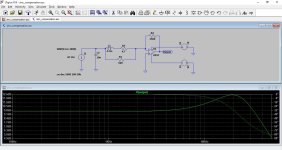
I played a bit with LTSpice...
That's the general idea for NOS droop correction, yes. However with the peaking at 20kHz it introduces a bit too much gain at 10kHz (theoretically should be +0.75dB) so to get a more accurate curve the peak normally needs to be above 20kHz, say around 24kHz and therefore the maximum boost a little bit over 3dB.
I played a bit with LTSpice...
I would suggest to not place anything between I/U conversion and DAC.
Add a peaking lowpass after the Op-Amp.
Say 10mH series inductor, 3.3nF +2k2 to ground after the coil.
Do a bit of curve fitting in the actual system to get a flat response at 10kHz.
Thor
I'd like to building this clock circuit with a 4.2336 MHz crystal. First time i am building one. Do i neede to adjust something?Ok, looking around, I decided to make a few small changes to the design, here the single TDA1541 sensible "Core".
View attachment 1370578
Key changes:
BC327 added to buffer the clock inputs of the 74F74, to avoid loading the clock. BC327 should be fine as follower at 50MHz. Internally each input is a Pin Diode (think 1N4148) and a 10k Pullup. So 4 clock inputs become a material load, we just don't want those currents to circulate across our input wiring. This way it's the base of a follower as load, with still decent beta at many MHz. Emitter load is ~ 2.5kOhm, base load less.
The attenuators and slew rate limiters are now "flying". This makes them a constant load regardless if Q or /Q are high (the other output is then low). This makes the 74F74 reclockers and signal conditioning mostly a constant load, if a chunky one at nearly 50mA. But they can now share the TDA1541 +5V and DGND with little issue.
So this overall simplifies things. DEM Clock is "Balanced Philips/Grundig" again with a flying balanced attenuator.
It may seem all a bit OTT and gilding the lily. Perhaps. I'm being quite minimalist by my standards.
I'm actually tempted to bring the MCK on board too, as the last element outside our control:
View attachment 1370584
In a lot of ways what I propose is not miles off from Johns work around SD Trans with TDA1541 DAC era.
Thor
OK, it makes sense.I would suggest to not place anything between I/U conversion and DAC.
Add a peaking lowpass after the Op-Amp.
Say 10mH series inductor, 3.3nF +2k2 to ground after the coil.
Do a bit of curve fitting in the actual system to get a flat response at 10kHz.
Thor
I'd like to building this clock circuit with a 4.2336 MHz crystal. First time i am building one. Do i neede to adjust something?
Probably need to change the inductors. Also, the original uses multiple crystals for better phase noise.
Thor
In the Philips CD player implementation with SAA7220 as the digital filter, that chip introduces a digital offset of 32LSBs, moving the glitch away from digital zero.
I wonder if all the bad critic on that chip, so called jitter, etc, were not in fact very unfair !
I can probably handle a cnc batch of "golden heart" type shielding to hand out. So it's shielded and decoupled physically from the board itself, on it's standalone board.
That's a good idea. Iancanada made cutting slots inside the PCB to make the crystal pcb floating inside. But anyway the board shoulld be current feeded and damped, so a coax very thin cable with very soft nylon body makes sense.
Like @Zoran said you want to avoid most possible you can some expternal vibrations to get there, hence the USB and chinch plugs on the cabinet and not directly soldered on the pcb as well.
Maybe to reduce the cost (cutting slot inside the pcb ?) you just can use two plastic rods for hanging the little clock pcb above the core pcb front end. and use a 1" ufl conection towards the main core board perhaps. Maybe overkill, I don't know.... Or better below the core board, suspensed to it, in order its power cable has no constraints, for instance lying on a foam sheet on the cabinet base plan. Cheap...
https://www.audiophonics.fr/fr/viss...ylon-male-femelle-m25x20-6mm-x10-p-11983.html
I always use plastic rods on soft double tape in my cabinet for the DAC pcbs : it looks less professional than metal road,,but the damping behavior is waaaaaaay better ! https://www.audiophonics.fr/fr/viss...t-pcb-adhesif-hauteur-11mm-unite-p-12997.html
Last edited:
My hypothesis is that its that chip (SAA7220) dirtying the supply that's largely responsible for the bad rap oversampling gets.
Thnx. Alsof for the nice work around the Pihilips TDA.I'd like to building this clock circuit with a 4.2336 MHz crystal. First time i am building one. Do i neede to adjust something?
Are calculations compareble to a (for example) choke loaded tube anode?
Say for a Bf862 R = 1/0.045 = 22Ohm in series with 2*pi*f* 0.00015? Phase: Tan (phi) = R /Z?
Can i simplefy by ignoring the diode and 330 ohm resistor?
My hypothesis is that its that chip (SAA7220) dirtying the supply that's largely responsible for the bad rap oversampling gets.
This plays a role.
However I would submit a few additional notes.
Keith Howard (IIRC) in HFB&RR & SP investigated pre/post/both ringing and found they were detected differently with certain types of signal, but not with music. If the test itself interfered to a degree was not tested or controlled for.
https://www.stereophile.com/content...biquitous-filter-filter-listening-impressions
Difference's with music were minimal and hard to isolate with music, however there are some interesting notes.
Further, DRA Lab's Douglas Rife (of MLSSA fame) published first a letter to Stereophile and later a little paper on the use of "poor digital filters" to improve DA Converters, arguably in the sense it is used here, no filter is the "poorest" digital filter and if we consider the paper to the logical endpoint....
http://www.mlssa.com/pdf/Upsampling-theory-rev-2.pdf
Pioneer had a long history of using a special digital filter dubbed "legato link" which remains in use in Pioneer's upper range DJ Gear (out of all places!!!) and likely contributes to the strong preference of many DJ's for Pioneer gear, over (say) the Range Serrato Boxes. I actually had occasion to modify Serrato boxes with Extra DAC PCB's that operate a "legato link like" very "poor digital filter" (and arguably were otherwise superior quality) which broadly made the Serrato Box comparable in sound quality to the TOL Pioneer DJ Player. Legato link explained by pioneer:
Anecdotally, prior to making my own digital gear, I had a strong preference Pioneer Legato Link equipped CD & DVD Players.
Theta also relied on such filters.
So I think there is a bit more here than just PSU noise.
I could also point to a number of devices of my own design, offering selectable digital filters, including non and listener reactions to the options, but that would be likely redundant.
Thor
PS, I omit to mention that British TLA thing, because A) most of the recordings claiming the benefit from "deblurring" on the recording side were not correctly deblurred and B) the claimed "unfolding" is basically the same as the "poor digital filters" discussed here and the software component running in the DAC get's bypassed by selecting "non oversampling", at that point all it does is turn the pink light on and off.
That's a good idea. Iancanada made cutting slots inside the PCB to make the crystal pcb floating inside. But anyway the board shoulld be current feeded and damped, so a coax very thin cable with very soft nylon body makes sense.
On the (likely permanently cancelled) "AMR Diablo" DAC, the clock and clock distribution was completely "carved out" from the main PCB and suspended on the SMA cables and special rubber O-Rings. Its somewhat visible in the picture below:
The extra mass-loading from the "CNC carved from solid copper and then gold plated" shielding lowered resonance frequency into Hz numbers and it was a well damped resonance IIRC.
Thor
Are calculations compareble to a (for example) choke loaded tube anode?
Pass. There are texts on this I remember reading, but not the details that I read.
My experience is that circuits we absolutely do not want to oscillate do so easily, readily and without trouble, while circuits designed as oscillators often refuse to oscillate at all costs...
I might just start by scaling the inductors by the frequency and leave the rest.
Thor
- Home
- Source & Line
- Digital Line Level
- Building the ultimate NOS DAC using TDA1541A