For PMBFJ620 in the datasheet, interchangebile S and D, that means that internal structure is symmetrical and the device could be used as P jfet too?
I tried some JFETS in "opposite" direction S-D, D-S and the Idss was almost the same?
I tried some JFETS in "opposite" direction S-D, D-S and the Idss was almost the same?

For PMBFJ620 in the datasheet, interchangebile S and D, that means that internal structure is symmetrical and the device could be used as P jfet too?
Yes, it's symmetrical, almost all J-Fet's are, it's inherent to the way the semiconductor is made:
Some specific ones for Capacitor Microphones and similar purposes cannot be reversed though.
And no, a reversed N-Channel J-Fet is still an N-Channel.
I tried some JFETS in "opposite" direction S-D, D-S and the Idss was almost the same?
Yup.
Thor
(I tried to test, before year or so, J108 (TO-92) version. It was huge Io with G and S connected to ground...
It is rated as MINIMUM Idss = 80mA!
Very good device, very low RdsON 8ohms,
Yes, I have used it mainly as Audio switch where 74HC40XX correctly applied have their capabilities exceeded. Once these were nixed I had to designs a distortion-free mosfet switch for high voltages or use J111/112/113 equivalents which have very high resistance, by comparison.
BUT it does not behave the same way in the simulations as in the real circuit...)
It does, for me. Maybe your model is NDFG?
Thor
Interesting, but all with overall looped feedback from the output.
Essentially two primitive discrete Op-Amp's, one current feedback the other voltage feedback. Both improvable.
Thor
Essentially two primitive discrete Op-Amp's, one current feedback the other voltage feedback. Both improvable.
Thor
You will find all the schematics all along this thread , search at i2s to simultaneous and dem 50 hz
.
.
Hi all,
Having completed a 801A Moglia preamp, I'd like to comeback to the idea of a TDA15141A based DAC and incorporate it into it. Sorry for not being "ultimate" but I want to try an old-school, minimalistic design for red-book CD: CS8414 feeding TDA1541A 50Hz DEM, passive I/V to 801A. I have a couple of questions to those with a 1st hand experience:
1) I have very good Jensen SUT's but they cannot stand any DC. Will a balanced operation, achieved with Pedja's I2S data split (each 1541A converts one channel, I think one calls it LL/RR) help to cancell the 2mA offset? I went through most of the thread trying to see a definite answer to that but was a bit hard.
2) Don't kill me for that but how important is to have a PCB at all for just the chip + surrounding caps? Say, I want a minimalistic module: the chip, DEM elctrolytic caps, 3-pin regulators, I2S attenuators. How bad would be a point-to-point, 3D assembly on a universal PCB, running different ground rails (DEM, GDND, Power, Output) star-grounded at pin 5?
Hello guys!
Have any of you had the opportunity to experiment 50hz DEM vs Grundig DEM?
I would be interested in hearing your impressions.
Thank you in advance.
Antonio
Have any of you had the opportunity to experiment 50hz DEM vs Grundig DEM?
I would be interested in hearing your impressions.
Thank you in advance.
Antonio
@tonimxp
FWIW I have used both the Grundig circuit and the 50Hz circuit. IMHO these are the two that sound the best, but I never heard them back to back so I could not recommend one over the other. I now use the 50Hz one. It was more of an evolution than a careful choice.
FWIW I have used both the Grundig circuit and the 50Hz circuit. IMHO these are the two that sound the best, but I never heard them back to back so I could not recommend one over the other. I now use the 50Hz one. It was more of an evolution than a careful choice.
Hi All
I have a arcam delta blackbox which utilises the tda1541a.

So far I've recapped it and NOSd it with the grundig DEM mod which I really like the sound of.

I tired various modules.

I've also been playing with parallel boards (this is a dual grundig dem parallel board).
My next plan is to use a modern input board which allows Bluetooth, optical, AES, coax etc at 24bit 192khz.

I'm a tda1541a newbie so just been learning as I go along and reading through the threads a bit This wonderful dac chip.
I'm a right in saying that the tda1541a can handle 192khz but needs to be in simultaneous mode? I can't just connect a 192khz 24bit board to the chip can I?
Just found this amazing item on AliExpress. Check it out!
£30.29 16%OFF | SAA7220 TDA1540 /TDA1541 Format Conversion Driver Module NOS/OS Switching 384K/24bit for Raspberry Pi
https://a.aliexpress.com/_EwJEkMt


My next though was to use a format convertor module, but this had led me down a rabbit hole now.
Can I use this module to drive a pair of tda1541a in parallel? Or is it better to use it on balanced mode.
Im trying to keep it simple hahaha.
Many thanks.
I have a arcam delta blackbox which utilises the tda1541a.
So far I've recapped it and NOSd it with the grundig DEM mod which I really like the sound of.
I tired various modules.
I've also been playing with parallel boards (this is a dual grundig dem parallel board).
My next plan is to use a modern input board which allows Bluetooth, optical, AES, coax etc at 24bit 192khz.
I'm a tda1541a newbie so just been learning as I go along and reading through the threads a bit This wonderful dac chip.
I'm a right in saying that the tda1541a can handle 192khz but needs to be in simultaneous mode? I can't just connect a 192khz 24bit board to the chip can I?
Just found this amazing item on AliExpress. Check it out!
£30.29 16%OFF | SAA7220 TDA1540 /TDA1541 Format Conversion Driver Module NOS/OS Switching 384K/24bit for Raspberry Pi
https://a.aliexpress.com/_EwJEkMt
My next though was to use a format convertor module, but this had led me down a rabbit hole now.
Can I use this module to drive a pair of tda1541a in parallel? Or is it better to use it on balanced mode.
Im trying to keep it simple hahaha.
Many thanks.
Attachments
Many thanks for your report@tonimxp
FWIW I have used both the Grundig circuit and the 50Hz circuit. IMHO these are the two that sound the best, but I never heard them back to back so I could not recommend one over the other. I now use the 50Hz one. It was more of an evolution than a careful choice.


Hi all,
I have attempted, first time ever, a 4-layer PCB design using CircuitMaker. It's clearly inspired by MV Labs and some of the Thorsten comments.
TOP Layer (Red) - Digital Signal: Input attenuators (MV Labs versions), DEM cap + res tracks
2nd (Brown) - DGND: DGND plane, GND of the input attenuators (thorugh 3 vias), pin 14 and pin 5 (together with 6 vias it connects all GND planes)
3rd (Cyan) - Analog signal + Power: +5V, -5V, -15V, GND for -15V connected to pin 5, DEM cap tracks
Bottom (Blue) - AGND: AGND for +/-5V and DEM caps, formed in a sort of a star connection to minimize crosstalks. Connected to DGND and -15V GND via 6 vias around pin 5 (there is no via stitching option in CircuitMaker hence it is what it is).
The only thing I could not route were the outputs. Will solder high purity Cardas litz directly from the TDA1541A pins to the output (J1), where output resustors will be soldered.
Comments very welcome!
HiCan I use this module to drive a pair of tda1541a in parallel? Or is it better to use it on balanced mode.
I use probably the same manufacturer model board. Long time ago
white one like in this example.
https://www.aliexpress.com/i/1005001614539604.html
I tried the boards in NOS mode without SAA chip.
(SAA7xxx OS filter needs a separate additional 12V power supply)
.
If You want NOS mode You have to pull out the SAA chip and connect the in-out pins under the chip on the PCB...
.
Board was working very well with I2S to TS14 bit mode up to 384KHz for TDA1540
+
Board was working good with 16bit for TDA1541A i think that was up to 192KHz.
.
But it is not for the ballanced mode. It has only +DATA L and +DATA R lines
You need inverters for data lines for balanced line. IF You want it...
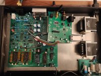
I received the new 4 layers board today , build it and test it this morning , I have this measurement for the moment
first image is left + right channel with 1 khz signal
second image is bck + lrck
third image is lrck + left or right channel without signal
fourth image is bck + left or right channel without signal
the schematic is the one John gave us in 2018 : I2S to simultaneous
I dont know where this bit is from when there is no signal ??
.
Last edited:
It is MSB inverted.
When no signal all bita are "0"
in TS format MSB is inverted so, the MSB goes from 0 to 1.
When no signal all bita are "0"
in TS format MSB is inverted so, the MSB goes from 0 to 1.
- Home
- Source & Line
- Digital Line Level
- Building the ultimate NOS DAC using TDA1541A