The 74AU1G74 is the only suitable CMOS D flip-flop I could find. Popular flip-flops like HC, F, and AC series add unacceptable jitter levels. You could also experiment with (P)ECL.
Have you measured the propagation delay between q and q prim of that flip flop? Most flipflops are constructed in such way that one inverter delay is incured between the outputs, this is usually not noted in the datasheets.
Fully agree. A PC is dirty, even batterie feeded. I went from PC-based I2S to (a modded) squeezebox reciever. Still using that to drive the DAC. Works excellent with Mk7, because the DAC's masterclock only drives the Xilinx processor to sync the WS en DATA lines with the bitclock. So only 4 wires are needed between DAC en SB. I didn't had the change to compare the sound against the SD-card. But i will next time i visit ECdesigns.
Could you give more details on the modded squeezebox? any links to the mod you did to feed the clock from the MK7 and take the I2S signal?
Any links in general to mod a squeezebox for I2S? I am new to this
What about direct fed i2s from Pace-Car reclocker?
I am doing something similar, using a Squeezebox to an Empirical Audio reclocker and then feeding i2s directly to the TDA1541A, with resistors in the path. The results seem very good to me. Is this a possible viable alternate solution?Fully agree. A PC is dirty, even batterie feeded. I went from PC-based I2S to (a modded) squeezebox reciever. Still using that to drive the DAC. Works excellent with Mk7, because the DAC's masterclock only drives the Xilinx processor to sync the WS en DATA lines with the bitclock. So only 4 wires are needed between DAC en SB. I didn't had the change to compare the sound against the SD-card. But i will next time i visit ECdesigns.
Give a look at this:
http://forums.slimdevices.com/showthread.php?t=55044&page=15
http://forums.slimdevices.com/showthread.php?t=55044&page=15
Could you give more details on the modded squeezebox? any links to the mod you did to feed the clock from the MK7 and take the I2S signal?
Any links in general to mod a squeezebox for I2S? I am new to this
Any links in general to mod a squeezebox for I2S? I am new to this
a little help:
Attachments
Have you measured the propagation delay between q and q prim of that flip flop? Most flipflops are constructed in such way that one inverter delay is incured between the outputs, this is usually not noted in the datasheets.
From the TI datasheet page 4:
CLK to Q, 0.8 ... 1.2ns @ 2.5V supply voltage and 15pF load
CLK to /Q, 0.7 ... 1.1ps @ 2.5V supply voltage and 15pF load
Propagation delay increases with capacitive loading:
CLK to Q, 1.4 ... 1.8ns @ 2.5V supply voltage and 30pF load
CLK to /Q, 1.3 ... 1.8ps @ 2.5V supply voltage and 30pF load
Reducing load capacitance below 15pF can further reduce propagation delay. In the MK7 I run the flip flops at approx. 2.5V with approx. 2pF load.
The generated jitter depends on the combination of propagation delay and noise on power supply / ground. Propagation delay is affected by load capacitance and supply voltage.
In general it is best to run the flip flop at power supply voltage that gives lowest propagation delay, and lowest possible load capacitance.
When a divider or reclocker circuit is build using this very fast logic, simply connecting the in / outputs together, will lead to high ground-bounce levels and poor jitter performance.
I used resistors to minimize ground-bounce. I placed them on programming inputs like the D input and on clock inputs that are not critical for direct output signal timing. I also used a shift-register divider so I didn't have to add extra logic (gates) that cause more interference.
Also note that the power supply for these flip flops needs to be extremely clean, similar to masterclock power supplies.
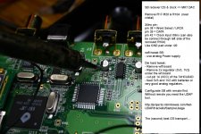
Latest development on the MK7 DAC, improved decoupling for the TDA1541A.
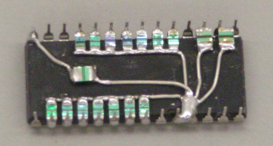
In order to optimize TDA1541A decoupling I soldered all decoupling caps directly to the pins of the chip as close to the IC housing as possible.
This way the added extra length of IC socket pins can be eliminated. The active divider decoupling pins no longer need to be connected to IC socket nor PCB. This further reduces leakage currents.
Isolators aren't perfect, so even a IC socket or PCB adds some leakage current. Problem is that with the TDA1541A the leakage current must stay well below 61nA. With average voltage of approx. 10V on the active divider decoupling pins this translates to approx. 164 Mega Ohms.
I attached a picture of the decoupling caps soldered to a S2 chip. Pin #1 is at bottom right.
Attachments

Hi,
Funny, when I made my first TDA1541 DAC around 12 Years ago, it looked a lot like your picture, except I wrapped the TDA 1541 into copper foil and used that as local ground-plane, as this reduced parasitic inductance... One could also use silver foil.
Ciao T
Latest development on the MK7 DAC, improved decoupling for the TDA1541A.
Funny, when I made my first TDA1541 DAC around 12 Years ago, it looked a lot like your picture, except I wrapped the TDA 1541 into copper foil and used that as local ground-plane, as this reduced parasitic inductance... One could also use silver foil.
Ciao T
From the TI datasheet page 4:
CLK to Q, 0.8 ... 1.2ns @ 2.5V supply voltage and 15pF load
CLK to /Q, 0.7 ... 1.1ps @ 2.5V supply voltage and 15pF load
0.1ns is still 100ps so for the first instant of every clock transition there will be a small glitch.
It would be possible to generate a true and inverted signal without incurring as much delay that might be worth perusing.
Why don't you sold the TDA1541A to the board?. Anyway, if you need to change something you can desold it and use it again in other board or something. I do this often, and like Thorsten L, I used this method a lot of years ago.
Kind regards,
Kind regards,
Latest development on the MK7 DAC, improved decoupling for the TDA1541A.
In order to optimize TDA1541A decoupling I soldered all decoupling caps directly to the pins of the chip as close to the IC housing as possible.
This way the added extra length of IC socket pins can be eliminated. The active divider decoupling pins no longer need to be connected to IC socket nor PCB. This further reduces leakage currents.
Isolators aren't perfect, so even a IC socket or PCB adds some leakage current. Problem is that with the TDA1541A the leakage current must stay well below 61nA. With average voltage of approx. 10V on the active divider decoupling pins this translates to approx. 164 Mega Ohms.
I attached a picture of the decoupling caps soldered to a S2 chip. Pin #1 is at bottom right.
I don't doubt for a second that it's not an improvement but what intrigues me is how the hell you managed to do it without frying the chip 😕
Hat's off to you for having the soldering skills....astonishing
I'll leave that one ' off ' the list of things to do
Andrew
Fet based negative regulator
Hi ECDesigns,
In post #3689 the fets specified seem to be hard to source / expensive. Any alternatives to SJ79 and 2sj74 without significant sacrifice in performance? One option I can think of could be 2sj103 instead of sj74.
Cheers!
Ravi
Hi ECDesigns,
In post #3689 the fets specified seem to be hard to source / expensive. Any alternatives to SJ79 and 2sj74 without significant sacrifice in performance? One option I can think of could be 2sj103 instead of sj74.
Cheers!
Ravi
Both these fets and the acrylic caps are in the category unobtainium...
I finally found the fets for 2.75 EUR (usually more, up to USD 8) at Reichelt.de, plus EUR 10 shipping...
The caps are from newark.com, so for me EUR 25 in shipping alone...
John, where did you get these babies? Maybe a GB would be worth while?
I finally found the fets for 2.75 EUR (usually more, up to USD 8) at Reichelt.de, plus EUR 10 shipping...
The caps are from newark.com, so for me EUR 25 in shipping alone...
John, where did you get these babies? Maybe a GB would be worth while?
I found the fets on the bay!
The caps should be available from your local Farnell
Latest development on the MK7 DAC, improved decoupling for the TDA1541A.
In order to optimize TDA1541A decoupling I soldered all decoupling caps directly to the pins of the chip as close to the IC housing as possible.
Nice work! At one point in this journey, I believe the thought was to keep ground lines from each bank of decoupling caps separate, and have nothing else on them. Do you now see an advantage to grounding directly to pin 5, or is it of no consequence to sound quality?
Problem is that with the TDA1541A the leakage current must stay well below 61nA. .
What is the audible impact of using caps with leakage current above 61nA? I used some SMT 8.2u organic polymer bypassed with 220 nf film. They have a leakage current of 3uA. They sound very good compared with the 220nf film alone.
Wlowes
The LSB (least significant bit) conducts 61nA when switched on.
So you'll only ever achieve 15bit coming out of the DAC.
The LSB (least significant bit) conducts 61nA when switched on.
So you'll only ever achieve 15bit coming out of the DAC.
Originally Posted by -ecdesigns- http://www.diyaudio.com/forums/digi...c-using-tda1541a-post2078040.html#post2078040
Bit15, DEM, (MSB), 2mA
Bit14, DEM, 1mA
Bit13, DEM, 0.5mA
Bit12, DEM, 250uAmA
Bit11, DEM, 125uA
Bit10, DEM, 62.5uA
Bit9, 31.25mA
Bit8, 15.625uA
Bit7, 7.8125uA
Bit6, 3.90625uA
Bit5, 1.953125uA
Bit4, 976.5625nA
Bit3, 488.28125nA
Bit2, 244.140625nA
Bit1, 122.070313nA
Bit0, (LSB) 61.035156nA
Note how low the LSB current is, only 61 nano amperes! LSBs can easily drop below system noise level when power supplies aren't super clean, and output circuit fails to maintain extreme low noise levels. And this is "only" 16 bit resolution. Imagine how critical 20 or even 24 bit systems will get. Using above current division, LSB in a 24 bit system would translate to 238pA!
Wlowes
The LSB (least significant bit) conducts 61nA when switched on.
So you'll only ever achieve 15bit coming out of the DAC.
Bit0-Bit15, I count 16 bits resolution. The challenge is an output stage wehre the lower bits aren't swamped by noise.
Most music hirez or otherwise only has a few bits resolution, a dynamic range on a commercial recording of 40db ~ 7 bits would be exceptional. Probalably the reason most of us reading this thread understand the TDA1541A understand the old sayin "its the first watt that matters most."
- Home
- Source & Line
- Digital Line Level
- Building the ultimate NOS DAC using TDA1541A