Wow that's great! I own you more than a coffee for this drawing.
–For vRef I was thinking to use a spare half AD712 that I have on the broader circuit. The datasheet indicates an output voltage of +/-13 aprox. Common-mode input voltage +14.5 / -11.5.
Otherwise I could replace it for an AD8397 or AD8620, I have both laying on the shelf–as long as it can also serve me as a +/-6V rail splitter, which is the current use of the other half.
I'm not sure what spec. should I look at, since all of them seem to cover 1.75V within their +/- range.
AD712 would be ruled out here because that -11.5V figure is with +/-15V rails. Meaning the input cannot approach within 3.5V of the -ve rail. AD8397 will probably work though I failed to find what its CM input voltage range was, its not rail-to-rail input.
I see... Negative common mode voltage must be closer than -1.75V to GND (Vs-) for it to work.
The AD8397's datasheet doesn't show VCM, but this official Q&A states 800mV from each rail 🙂
https://ez.analog.com/amplifiers/w/documents/1768/ad8397-input-voltage-ranges-datasheet-rev-a
So I'll try with it and hands to work. Keep you updated.
The AD8397's datasheet doesn't show VCM, but this official Q&A states 800mV from each rail 🙂
https://ez.analog.com/amplifiers/w/documents/1768/ad8397-input-voltage-ranges-datasheet-rev-a
So I'll try with it and hands to work. Keep you updated.

I soldered two towers, 11 chips in two groups of 5/6. I've only been testing in the last hours and the DC filter doesn't seem to be working yet. A scratching noise comes and go, same that can be heard when HP is connected directly to the DAC output.
Vref opamp seems to be working, I can read 1.76V stable while sounding. Connected to HPs GND.
Current sink also seems to be working. I increased the resistor to 150ohm because now I'm using only 5 chips for testing (so I don't go deaf with the noise). Multimeter between 150ohm sense-resistor and GND reads 4.4mA, half of the total estimated consumption -> (5mW / 63) squared = 9mA.
Common ground to digital source is not the problem, noise persists when unplugged.
I'll keep on trying and breadboard it all again, maybe digital lines are too long... Just reporting, maybe some ideas come.
Sharing pics of the towers they look good. Just glued them with epoxy first, then bended the legs down and dropped solder thought each rail.
There's no need to parallel all the pin7s, that may save you a little time on the next build. When they're unconnected they serve as a useful health check for the DAC, when that voltage is out of spec the DAC's normally a dead one. But there are other failure modes beyond that which could be the cause of your crackles.
Its a good idea to buzz out all the pins from top to bottom with a continuity checker to weed out dry joints.
Its a good idea to buzz out all the pins from top to bottom with a continuity checker to weed out dry joints.
I've been doing some process here, just needed some time and calm to plug everything correctly and source back the problems.
Noise was coming massively from the 78L05 regulator. I replaced it by a zener + current source and voilá, it sounds clean and quiet. I followed the circuit that you @abraxalito shared with me in page 3, which seems to be the proper voltage regulator for this. I've read that zener are noisy but I don't hear any noise from it–although I'm still at a very low level.
When I add caps to the VDD of the DAC they sound nasty, no matter what I put on. I can hear current fluctuating along the cap so I simply removed them. Only cap in use is the vref one (220u Nichicon). No caps at the output either. It works fine with an I/V resistor of 510ohm and a 220u output cap, but even better without any, DAC outputs direct on the headphones. Strange enough I don't hear any effect from DC current, if noise should be there I cannot perceive it and the sound is very crisp so I wish to leave like this.
I tried the DC filter with a current sink in any case. For a 4x DAC I used a 510ohm load resistor, which sinks 1.22mA. Then headphones take around 1.88mA (measured) at the positive. The only problem is that the negative side seems to be a bit noisy, I suppose noise produced by the opamp that sets GND at 1.75V. If I sink the whole current down I hear a lot of noise (only when digital line is playing something).
I wonder if, since I hear no DC noise, a DC filter is really necessary in this case. Also, what to do next to increase current and make this louder.
I'm still testing with 4x DAC pilled. What is the "sonic" effect of pilling up more DACs? Does it bring details to the fore or the other way around? Soundstage increases or decreases? Just asking for a subjective opinion. I'm in the dilemma of adding an amplification stage or sticking to a huge tower of DACs. I plan to also drive some small in-ear monitors that are very low in impedance. For example, for some 18Ω 118dB/v earphones (Sennheiser IE 600) @ 110dBSPL a calculator says 1.27vpp and 14mA (x2) are needed. Voltage is within my range but current would mean 28x DACs. But, is that really the case? I can't understand how come such little transducers consume so much current. Or is it that earphones operate at much lower dBSPL than headphones? A current amplification stage, if necessary, could be added maybe with a current source/sink or a voltage follower circuit? Just getting into it 😉
PD: Got rid of the popping noise mentioned before too. It came from an ADC board intentionally off (ungrounded) that shares the digital lines with the DAC. Once I grounded it or fully disconnected it glitches were gone.
I've read that zener are noisy but I don't hear any noise from it–although I'm still at a very low level.
Zeners can be quiet, it all depends. Certainly compared to bandgaps they seem quiet. The lowest noise (most stable) voltage references I've come across use buried zeners, for example LTZ1000.
I'm still testing with 4x DAC pilled. What is the "sonic" effect of pilling up more DACs? Does it bring details to the fore or the other way around? Soundstage increases or decreases? Just asking for a subjective opinion.
More chips makes it louder, that's the primary effect. Secondly, more chips reduces noise. The noise reduction I find most noticeable in the lower frequencies, it increases the intelligibility of the ambient acoustic.
I'm in the dilemma of adding an amplification stage or sticking to a huge tower of DACs. I plan to also drive some small in-ear monitors that are very low in impedance. For example, for some 18Ω 118dB/v earphones (Sennheiser IE 600) @ 110dBSPL a calculator says 1.27vpp and 14mA (x2) are needed. Voltage is within my range but current would mean 28x DACs. But, is that really the case? I can't understand how come such little transducers consume so much current. Or is it that earphones operate at much lower dBSPL than headphones? A current amplification stage, if necessary, could be added maybe with a current source/sink or a voltage follower circuit? Just getting into it 😉
Headphones respond to power and given those are only 18ohm impedance the power with the same current is going to be much lower than with your 63ohm ones.
Thank you for answering that very long report.
I have 63ohm 106dB/mW headphones that need 0.8vrms and 12.6mA to reach 116dBSPL = 110mW.
Will both sound the same loud provided the requirements of the second? Earphones will take the 10mA needed from the spare voltage? Say, convert spare voltage into demanded current internally?
If that's the case, circa. 24x DAC should be enough for both 🙂
If say, some 16ohm 107dB/mW earphones I wan't to buy... 🙂 (old Senn. E 800). They need 0.35vrms and 22mA to reach 116dBSPL = 110mW.Headphones respond to power and given those are only 18ohm impedance the power with the same current is going to be much lower than with your 63ohm ones.
I have 63ohm 106dB/mW headphones that need 0.8vrms and 12.6mA to reach 116dBSPL = 110mW.
Will both sound the same loud provided the requirements of the second? Earphones will take the 10mA needed from the spare voltage? Say, convert spare voltage into demanded current internally?
If that's the case, circa. 24x DAC should be enough for both 🙂
The efficiency ratings are normally (not always) stated in dBASPL/mW. So if you have two sets of HPs at 116dB/mW they'll sound equally loud at the same input power. The impedance will determine what volt/current are needed for that level of power input.
Here goes what I ended up going for, after much trials and learnings. Definitely I got the best results from a direct current connection to headphones. The drawback of the design is that the output can only provide headphones/speakers–not other devices, but that was the initial idea.
I found that no other caps than vRef are actually needed. But the constant current/zener voltage regulator circuit is powered directly from a battery stack and the I2S source (MC) has its own independent battery.
The output is loud enough for the specs indicated in the drawing. With 63ohm 106dB/mW headphones it is loud enough to be painful (112dBSPL). It sounds crystal clear, quite detailed and with an impressive beautiful soundstage. More 3D than anything I've heard, which is the NOS DAC effect of course but lacking an amplification stage adds detail to it. Compared to a 8xTDA1387 + JLH Class-A headphone amp I've been using over the last year, here you feel the lack of power of course but details can be perceived more precisely, in my (forgive the audiophilia) humble opinion.
Microcontroller in use is a 'Teensy 4'. Playing directly from SD cards is good, over USB can present problems and it is limited to 44.1kHz. The older model is seemingly a bit more stable so I'm currently moving there and starting to think also of other possibilities that can bring this to another level. I've seen a few projects based on ESP32 lately. @abraxalito mentioned something on oversampling and I wonder which MC would he recommend for this purpose, or where to start. I ignore everything that has to do with licensing, but I guess Teensy is a licensed brand that brings in some (legal) limitations, for example when it comes to integrate this DAC design into broader projects. Soundwise, a tiny bit of oversampling would do some good to it. I tried shortly with a 4x oversampling code with the Teensy and it all became extremely flat, too much, but details were highlighted and revealed.
Thank you again Abraxalito and Hifiamps for all the help. I consider my original idea/need realised.
Very pleased to see you achieved your aim with this project, great job!
As regards oversampling, I've written code for Cortex M0 and M3 in the past. I'm going to try porting that code to the RP2040 (M0+) as that's cheap and readily available in the current climate of MCU shortages worldwide. As RP2040 runs at 133MHz I'm certain there's enough CPU horsepower available. I am guessing the Teensy is a Cortex M4?
As regards oversampling, I've written code for Cortex M0 and M3 in the past. I'm going to try porting that code to the RP2040 (M0+) as that's cheap and readily available in the current climate of MCU shortages worldwide. As RP2040 runs at 133MHz I'm certain there's enough CPU horsepower available. I am guessing the Teensy is a Cortex M4?
Yes, Teensy 3.x is M4 based (180MHz). Teensy 3.6 is a solid board, with enough RAM and 4-bit SD port to write audio. Hope they start producing it again, in my experience it is more stable than IMXRT-based (600MHz) Teensy 4 and 4.1 for audio work.
My biggest frustration with Teensy is the limitation to 44.1kHz/16bit. Inconvenient to combine with files and workflows that use higher sample rates. But it’s been a life saver for me in general.
Isn’t problematic that the RP2040 doesn’t support I2S (as I see). And have you published you oversampling code for M0-3 somewhere? I’m quite curious about it.
You're right that RP2040 doesn't have any built-in I2S peripherals. What it does have is a couple of SPIs which will work in TI mode and I've had the same peripheral driving my DACs years ago when I made a digital filter out of an LPC1114. The SPI peripheral used is designed by ARM so is the same in both LPC1114 and RP2040. Its not ideal though as it needs some external logic to make it work.
The more promising route (at least for I2S output) is using the PIO functionality of the RP2040. I pointed out on another thread that there's now code available on Github for the PIO to input and output I2S : https://www.diyaudio.com/community/threads/cheap-arm-mcus-for-rbcd-audio.350074/post-7020654
I didn't publish the code for my M0/M3 digital filter no. It didn't have a robust I2S output through the SPI port, it would sometimes glitch as my method to hack the generation of LRCK by using a timer was too flakey. I feel sure that the PIO functionality on RP2040 could generate LRCK to accompany the SPI output though, or PIO could bypass the SPI output altogether.
Hi Abrax,
i’ve been gazing at the RP2040 and looks good. There’s a small breakboard version that looks perfect for minimal diy projects: PGA2040.
My current level of programming skills is still basic though and my needs quite a few (defined) ones. As mentioned I’m trying to build a decent recorder/interface so the list is bit demanding: adc/dac via i2s, usb i/o, sd card writer/player with wav headers and digital volume control (+play, rec buttons). All this preferably at 48kHz 24bit (for recording, playback at 16bit is enough and perfect now with this DAC).
All this is almost achieved with the teensy and their library, except for the M4 versions not being sold anymore and the library’s unescapable 16bit limitation.
Would I start programing an RB2040 for the aforementioned functions, would it better be done in microphyton or C/C++? Sorry for the ignorance but I haven’t found yet any similar projects to do what I need and I see that the MCU is designed to work with both languages.
I’m sorry also if this is going bit off-topic now, for future visitors coming after the original thread subject.
Cheers!
Domingo
I don't have any experience of recording and playback from TFcard so its rather above my paygrade to suggest which language would be most appropriate. Python is definitely slower than C because its interpreted that's about all I know. I plan to stick with assembler for my DSP needs, the impression I've gotten so far (from watching YT) is the SDK for C/C++ easily supports assembler so I'll be going that route.
This is all part of your project so I don't see that its going off-topic, you could ask the mods to rename the thread 'Designing and building a portable tda1387 dac/player' and that'll cover it nicely.
This is all part of your project so I don't see that its going off-topic, you could ask the mods to rename the thread 'Designing and building a portable tda1387 dac/player' and that'll cover it nicely.
Hi @abraxalito
I've been experimenting again with this DAC design quite a lot lately, mostly because the last solution posted (#110) sounds great, but it consumes too much battery power and it is not loud enough for monitoring sound. So I went back to one of the designs with opamp I/V stage / HP amp...
Shifting the ground of the DAC with a zener worked to an extent. With the DAC at 5.6V and outputs at 2.5V I get a nice loud 1.5V swing–the opamp ve+ at 5.5V with a fixed reference. The problem however is the ground shifting zener. Voltage is inconsistent, with any zener between 3-3.9V I get 4V under load. It also gets quite hot, since I have an ADC running in parallel that has to be grounded on it as well, as you indicated me. In total ADC and 6xDAC are passing around 50mA through it and I'm afraid of the noise that this zener is actually producing, as ADC and DAC grounds meet there.
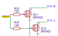
So I went back to your mention of Mosfets to increase the DAC's VDCC. Solving the source of the problem this way might mean avoiding all the troubles of ground lift and the power waste related to it 🙂 Surfing your blog I think to have found an application of this in your Dorati. Picture attached. I'm I correct? Does it suffice to add a Mosfet simply in this way to increase VDCC? I guess MREF is the desired VDCC... Up to what voltage is it then increased (supposing DAC VCC at max. 6V, with a min. 1.5Vp swing). A pair of 2N7002 are on the way to experiment.
Hope you are doing great,
Domingo
I've been experimenting again with this DAC design quite a lot lately, mostly because the last solution posted (#110) sounds great, but it consumes too much battery power and it is not loud enough for monitoring sound. So I went back to one of the designs with opamp I/V stage / HP amp...
Shifting the ground of the DAC with a zener worked to an extent. With the DAC at 5.6V and outputs at 2.5V I get a nice loud 1.5V swing–the opamp ve+ at 5.5V with a fixed reference. The problem however is the ground shifting zener. Voltage is inconsistent, with any zener between 3-3.9V I get 4V under load. It also gets quite hot, since I have an ADC running in parallel that has to be grounded on it as well, as you indicated me. In total ADC and 6xDAC are passing around 50mA through it and I'm afraid of the noise that this zener is actually producing, as ADC and DAC grounds meet there.
So I went back to your mention of Mosfets to increase the DAC's VDCC. Solving the source of the problem this way might mean avoiding all the troubles of ground lift and the power waste related to it 🙂 Surfing your blog I think to have found an application of this in your Dorati. Picture attached. I'm I correct? Does it suffice to add a Mosfet simply in this way to increase VDCC? I guess MREF is the desired VDCC... Up to what voltage is it then increased (supposing DAC VCC at max. 6V, with a min. 1.5Vp swing). A pair of 2N7002 are on the way to experiment.
Hope you are doing great,
Domingo
Attachments
I'm unclear what you mean by 'VDCC' in relation to the DACs. If you mean its pin5 voltage then that can't increase above 6V. Perhaps you mean the DAC's output compliance voltage, this is increased through use of MOSFETs.
The MOSFETs increase the available swing on the current output, which is moved to the drain terminal of the FET. The voltage at the DAC chips' outputs is (MREF - Vgsth) where the latter is the gate threshold voltage of the FET.
The tricky thing with using 2N7002 is the Vgsth varies a lot between different examples leading to choice of MREF being fraught with difficulty. So I have given up using that particular part, now I use Rohm RYC002N05 : https://www.mouser.co.uk/datasheet/2/348/ryc002n05-e-1873326.pdf This FET is a beauty and its consistency of Vgsth is impressive.
MOSFETs alone though can't provide a full solution, you'll also need biassing current sources (to 0V on the FET source, to VDD on the drain) to keep the FETs in their active region.
I'm sorry for the imprecision, with VDCC I referred as you guess to the voltage at pin5. Should I assume then that with a MOSFETs stage on the DAC's output I could set pin5 at 5.5V and still have a voltage swing from 4-7V? So the output swing of the MOSFETs can go even higher that the DAC's 6VCC?
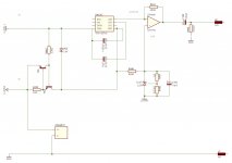
Here is where I am (schematic attached). To avoid the ground shift zener's dissipation and noise, I use the + of my first Li-Ion as ground for the DAC instead. Batteries voltage are written at min. voltage (3V). A TL431 defines a 2.5V reference for the DAC's pin5. This shows as 5.5V to the opamp ve+, which I think is the ideal midpoint for some opamps limited to -Vs +4 input common-mode voltage.
The setup sounds good, plenty loud and clean. The only disadvantage I see is that batteries 2-3 will obviously discharge more than 1. My ADC is loading 22mA on them additionally... I will try with only 1xDAC so the load comes down to the bare min. at least.
Attachments
Should I assume then that with a MOSFETs stage on the DAC's output I could set pin5 at 5.5V and still have a voltage swing from 4-7V? So the output swing of the MOSFETs can go even higher that the DAC's 6VCC?
Yes, with a MOSFET acting as cascode on the DAC's output, your output voltage swing limit becomes the MOSFET's breakdown voltage (50V for the Rohm FET) rather than the DAC's output compliance limit.
Thank you! I will have to study how to bias the MOSFETs then, cascode means at least two of them per channel as I see. If pin5 would be at 5.5V, which I intend, then the voltage swing would be too high for my headphones I'm afraid–since 2.5V seems already enough. How would you attenuate it then later? With an extra series resistor to limit current? The obvious thing would be to lower pin5 voltage but then I hit the opamp's minimum input voltage limit.
A few other questions. In a previous post you mentioned a compensation resistor, from between DAC output and the opamp's inverting input to ground. A value of 1.8K you said. What is the purpose of that resistor? To compensate DC current at ve+, so the output of the opamp is free of DC and no output cap is needed?
A few other questions. In a previous post you mentioned a compensation resistor, from between DAC output and the opamp's inverting input to ground. A value of 1.8K you said. What is the purpose of that resistor? To compensate DC current at ve+, so the output of the opamp is free of DC and no output cap is needed?
- Home
- Source & Line
- Digital Line Level
- Building a portable I2S 4x TDA1387 DAC