
Maybe it is yoo much ohms? Bare in mind that there is 4 or more inputs with own capacitance. Probably this 470ohms hardly "rounding" the edge from 0 to 1. Offcourse it is for cuttinf out unwanted peaks and for signal integrity but i think that is too much You will loose the sleave rate... Best way is to measure with the scope after that R. Could be small multiturn pot, then just cut out the spikes.I use a 470R mounted close to each of the I2S pin
Yu can round the square down to Level of IC taking Vin as HI but not more. That is stated in the PDF
...
But if You want to attenuate digital lines that is the another thing. Use some other way and stay in the borders with LO and Hi logic levels in the datasheet?
Last edited:
Yes and maybe to add another 100nF and 10nF in parallel? The smallest value as close to +V pinAdding a 1uF acrylic film SMD cap in parallel to C64 is beneficial.
?
I think not? But @abraxalito will answer for sureCan the stack of four TDA1387 share C62? I'm not sure.
Wow, took me a lot of searching to find the context for that - right back on the first page. Yes no problem with sharing C62 across a whole stack of chips.
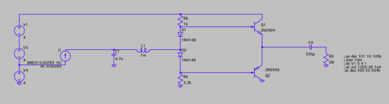
What is the reason @abraxalito an LR filter is not working when the inductor goes directly at the DAC's output–so biasing resistors R6/R8 can form the filter. With an effective resistance of 1k here I don't get (for testing purposes) the expected fc at 15k.
Is it rather recommended to include an "additional" I/V resistor before the inductor? Would that also avoid the inductor from increasing the output compliance of the DAC?

Is it rather recommended to include an "additional" I/V resistor before the inductor? Would that also avoid the inductor from increasing the output compliance of the DAC?
Attachments
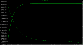
The AC analysis does show up that there's no attenuation at HF when feeding an inductor from a current source - I get that too on my (simpler) sim of CCS -> L -> R. Which is kind of surprising at first glance.
To see what's happening, look at the voltage on the DAC output as the frequency increases - it increases too. So from a voltage perspective there is attenuation - so the LR is operating just as you'd expect - but the input voltage increases and the output stays flat. Rather than the input voltage staying the same (as it would with a voltage source) and the output decreasing with frequency.
Just adding a cap on the DAC output solves this and gets you back to where you want to be, having an HF roll-off. Looks to me that 10nF (in parallel with your current source) is about right with R=1.35k. But that's without any R in the 10mH so you'd best find an inductor you like and get its ESR to plug into the sim.
Adding a resistor before the inductor will work but that wastes DAC output current (and hence battery in this application) so an inferior solution to a capacitor there.
Thank you @abraxalito, the small cap between inductor and DAC was extremely useful and the part I was missing. I noticed how the voltage at high frequencies increases DAC side without it, also that when the cap is not big enough a peak at the cut-off frequency is formed. I think this behaviour has been used in some of your applications before to compensate for the 'NOS droop' at 20kHz.
Finding suitable shielded inductors is quite a challenge–especially to import from latinamerica where I'm located at the moment. Best I found are some generic 1mH SMD CDRH74. Height is not a problem for me below 13mm, but surface is limited and these are conveniently 7.5x7.5mm. ESR is normally 6ohm.
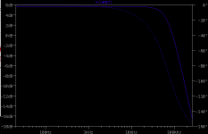
In this design I added a fifth DAC chip and increased I/V effective resistance to +/-680ohm, which shifts the filter fc to a slightly higher frequency. Combined with 4.7n before the inductor the slope reaches around -22dB at 260kHz, which should be the Nyquist frequency when 4x oversampling. If images at this level with be audible is hard for me to tell, but it is difficult to achieve much with a relatively small inductor.
Finding suitable shielded inductors is quite a challenge–especially to import from latinamerica where I'm located at the moment. Best I found are some generic 1mH SMD CDRH74. Height is not a problem for me below 13mm, but surface is limited and these are conveniently 7.5x7.5mm. ESR is normally 6ohm.
In this design I added a fifth DAC chip and increased I/V effective resistance to +/-680ohm, which shifts the filter fc to a slightly higher frequency. Combined with 4.7n before the inductor the slope reaches around -22dB at 260kHz, which should be the Nyquist frequency when 4x oversampling. If images at this level with be audible is hard for me to tell, but it is difficult to achieve much with a relatively small inductor.
Attachments
Last edited:
Thank you @abraxalito, the small cap between inductor and DAC was extremely useful and the part I was missing. I noticed how the voltage at high frequencies increases DAC side without it, also that when the cap is not big enough a peak at the cut-off frequency is formed. I think this behaviour has been used in some of your applications before to compensate for the 'NOS droop' at 20kHz.
Yes - in filter terms varying the cap varies not only the fc (cutoff or corner frequency) but also the damping and damping is directly related to the 'Q' of the filter. We normally want a Q around 0.7 or so for a flat response. Increasing the Q gives peaking at the corner frequency and that is indeed used to correct NOS droop in some of my (and others') filter designs.
I take it those are Sumida. I've found Sumida inductors look pretty good on paper and are cheap but when I came to measure mine the HF losses were too high to be useful in many filters. TDK are much better but perhaps you can't get those so easily. For 1mH, the SLF7045T is hard to beat and ESR is under 3ohm.Finding suitable shielded inductors is quite a challenge–especially to import from latinamerica where I'm located at the moment. Best I found are some generic 1mH SMD CDRH74. Height is not a problem for me below 13mm, but surface is limited and these are conveniently 7.5x7.5mm. ESR is normally 6ohm.
https://www.aliexpress.us/item/3256803454018763.html
In this design I added a fifth DAC chip and increased I/V effective resistance to +/-680ohm, which shifts the filter fc to a slightly higher frequency. Combined with 4.7n before the inductor the slope reaches around -22dB at 260kHz, which should be the Nyquist frequency when 4x oversampling. If images at this level with be audible is hard for me to tell, but it is difficult to achieve much with a relatively small inductor.
The Nyquist at 4XOS would be 4X the Nyquist at NOS (22.05kHz) so 88.2kHz. When it comes to images, the first images appear at 176-20 = 156kHz. A 2nd order filter won't make much of an impact by that frequency.
The Nyquist at 4XOS would be 4X the Nyquist at NOS (22.05kHz) so 88.2kHz. When it comes to images, the first images appear at 176-20 = 156kHz. A 2nd order filter won't make much of an impact by that frequency.
Maybe I shouldn't have mentioned my insufficiently studied guess on Nyquist and image frequencies before asking. I take your calculation for granted 🙏, as spending much time into sampling theory defeats me at the moment.
As previously mentioned, I'm planning to borrow a code for 4x oversampling which includes an optional digital filter -> designed for TDA1543 PT8211 but seems to work fine on the TDA1387 as well. Leaving that as a background and having realised that including a capacitor between inductor and I/V resistors seems to form a 3rd order filter, it seems more reasonable to me now focusing the filter on correcting the droop. Are you still of the opinion that LC filters give strange coloration when doing that? Is the correction curve (Q0.7?) better suited to a 2nd or 3rd order filter? Are you aware of bigger inductors (ie. 5.6-10mH) offered on Ali (or other distributors) you would recommend?
I'm not fluent in C but from your link it looks as though you have a choice of linear or CIC interpolation. I'd not heard of the latter before so I'll investigate that somewhat. I was looking to see if he was using a traditional FIR and didn't see any evidence of that like an array of coefficients.
As for my blog link going back 10 years, there I'm talking about higher Q than I've been using of late - I say that the filter needs 8dB of peaking. Nowadays I get away with about half of that figure, perhaps in the old days I was more rigorous about getting the response flat to 20kHz whereas these days my hearing goes nowhere near that high. I think the correction curve can be implemented on any order filter from 2 upwards.
Aliexpress isn't a rich resource for >1mH inductors, the ones I've seen which do go into that range seem to be unshielded so I can't recommend them. Even Taobao has a poor selection, you're better off going to Mouser for Fastron or Bourns.
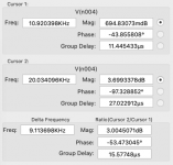
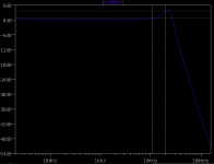
Bourns RL181S would have to be–I managed to make space for it. With Q 0.7 and "peak" at 20kHz, -3dB calculates I think at 10.92kHz on the hearable side. This seems to be achieved nicely by the following figure which also brings down the first images to -50dB, maybe the digital filter wouldn't even be much necessary > 68n - 10mH - 68n. Please correct me if I am wrong.I'm not fluent in C but from your link it looks as though you have a choice of linear or CIC interpolation. I'd not heard of the latter before so I'll investigate that somewhat. I was looking to see if he was using a traditional FIR and didn't see any evidence of that like an array of coefficients.
As for my blog link going back 10 years, there I'm talking about higher Q than I've been using of late - I say that the filter needs 8dB of peaking. Nowadays I get away with about half of that figure, perhaps in the old days I was more rigorous about getting the response flat to 20kHz whereas these days my hearing goes nowhere near that high. I think the correction curve can be implemented on any order filter from 2 upwards.
Aliexpress isn't a rich resource for >1mH inductors, the ones I've seen which do go into that range seem to be unshielded so I can't recommend them. Even Taobao has a poor selection, you're better off going to Mouser for Fastron or Bourns.
Attachments

Just a comment on oversampling/upsampling. With the TDA1387 x 8 NOS DAC, upsampling has always sounded worse to me than the original file. That is until I used PGGB which "use extremely long windowed Sinc filters". I really don't have enough computer power to adequately use the program (128 GB minimum RAM plus virtual memory is recommended, so I have been only able to process files <15 minutes), but upsampling 8X up to 384k (up to 186 million taps), I cannot hear the difference between the original file and the upsampled one. I have 65 yo ears, so that is a factor. Similar to the findings in What do you think makes NOS sound different?
Bourns RL181S would have to be–I managed to make space for it. With Q 0.7 and "peak" at 20kHz, -3dB calculates I think at 10.92kHz on the hearable side. This seems to be achieved nicely by the following figure which also brings down the first images to -50dB, maybe the digital filter wouldn't even be much necessary > 68n - 10mH - 68n.
Ran a plot and found the boost at 20kHz is right (3.2dB) but the shape of the curve itself is too narrow, gain at 10kHz for example should be 0.75dB but only 0.25dB with this circuit. I made the shape wider and increased the 10kHz gain by reducing the cap values to 5.6n. Since my hearing goes nowhere near 20kHz I tend to pay more attention to 10kHz where I still have some left.
@hifiamps - there's going to be a difference in frequency response when going from NOS to 8XOS which makes the sound a tad more airy. At least it does to my ears but really not so easy to notice without direct switching back and forth.
Yes, I was surprised that I could not hear the difference with elimination of sinc droop. I have only converted a few files. I can't immediately switch back and forth between the two, just playing passages of one file then the other. I should try some single blind testing. The other difference with 8XOS is that images are pushed to far ultrasonic. I can't hear problems with images in the near ultrasonic range with NOS. I feel fortunate.
An interesting finding with the upsampled files is a very low level noise from 49kHz to 192kHz, maybe dither noise? Seen in the frequency spectrum plot and also in the bottom chart which appears as a field of purple on the black background.
.flac_report.png")
An interesting finding with the upsampled files is a very low level noise from 49kHz to 192kHz, maybe dither noise? Seen in the frequency spectrum plot and also in the bottom chart which appears as a field of purple on the black background.
Last edited:
Having recently done comparisons between NOS without filter and with filter I hear clear differences. I guess I can only attribute them to images being heard indirectly via intermodulation as I can't think of another explanation. Perhaps its that my amps are more susceptible than others' to IMD as there are guys on this forum who hear nothing wrong with NOS DACs without an anti-imaging filter.
Ran a plot and found the boost at 20kHz is right (3.2dB) but the shape of the curve itself is too narrow, gain at 10kHz for example should be 0.75dB but only 0.25dB with this circuit. I made the shape wider and increased the 10kHz gain by reducing the cap values to 5.6n. Since my hearing goes nowhere near 20kHz I tend to pay more attention to 10kHz where I still have some left.
Do you know @abraxalito how to achieve an accurate curve using more standard capacitor values? I'm using MKS and FKS from WIMA and 5.6n is not available. Only 4.7n and 6.8n around that value and very easy to obtain. Otherwise, any 5.6n capacitor type/brand you would particularly recommend?
When you can only get E6 values then the normal route is to parallel smaller caps. I'd do 4.7n and 1n in parallel to get close enough to 5.6n.
I made several experiments today that I would like to share.
Test board is based on a Teensy that allows oversampling and has two I2S ports. On the first one I set 8x TDA1387 chips with a flat passive filter published by @abraxalito in post #12 of this thread. Only difference is I used an 82ohm I/V resistor instead of 100ohm, it fits better my amp. Also, I used a 2n cap instead of 3.9n at the end of the filter's chain, this way I got a very flat response with a -3dB droop going from around 5kHz to 20kHz.
Sampling rate was 44.1kHz, tested with oversampling alone and digital filter.
1. 8x TDA1387 / NOS @ 10kHz.

2. 8x TDA1387 / 4x oversampling @ 10kHz.

3. 8x TDA1387 / 4x oversampling + CIC filter @ 10kHz.

I noticed a mistake on the breadboard later that might be responsible of sinewave errors, but it seems to me that 4x oversampling and digital filter get rid very effectively of distortion. I'm not sure if that distortion is solely produced by sampling images or harmonics of a different kind, this is quite new to me.
On the second I2S port I installed a 24x chips tower (got a bit hot) directly on some 63ohm headphones. No I/V resistor and all vref pins floating. Against my belief, the result was not very good. Quite a lot of noise, which I can attribute to DC current because of lacking an output capacitor or/and temperature of the tower. Also a ladder of samples can be seen when looked closely.
24x TDA1387 / I-out on 63ohm @ 1kHz


So the I-out idea is not as simple as pilling up many chips and using headphones as an I/V resistor. @abraxalito mentioned in this thread that for I-out a current sink to create a negative current swing is needed, but I'm not sure if that would also take care of noisy DC current or soften the ladder I'm seeing/listening.

Test board is based on a Teensy that allows oversampling and has two I2S ports. On the first one I set 8x TDA1387 chips with a flat passive filter published by @abraxalito in post #12 of this thread. Only difference is I used an 82ohm I/V resistor instead of 100ohm, it fits better my amp. Also, I used a 2n cap instead of 3.9n at the end of the filter's chain, this way I got a very flat response with a -3dB droop going from around 5kHz to 20kHz.
Sampling rate was 44.1kHz, tested with oversampling alone and digital filter.
1. 8x TDA1387 / NOS @ 10kHz.
2. 8x TDA1387 / 4x oversampling @ 10kHz.
3. 8x TDA1387 / 4x oversampling + CIC filter @ 10kHz.
I noticed a mistake on the breadboard later that might be responsible of sinewave errors, but it seems to me that 4x oversampling and digital filter get rid very effectively of distortion. I'm not sure if that distortion is solely produced by sampling images or harmonics of a different kind, this is quite new to me.
On the second I2S port I installed a 24x chips tower (got a bit hot) directly on some 63ohm headphones. No I/V resistor and all vref pins floating. Against my belief, the result was not very good. Quite a lot of noise, which I can attribute to DC current because of lacking an output capacitor or/and temperature of the tower. Also a ladder of samples can be seen when looked closely.
24x TDA1387 / I-out on 63ohm @ 1kHz
So the I-out idea is not as simple as pilling up many chips and using headphones as an I/V resistor. @abraxalito mentioned in this thread that for I-out a current sink to create a negative current swing is needed, but I'm not sure if that would also take care of noisy DC current or soften the ladder I'm seeing/listening.
Last edited:
- try to load with classic Riv value R to compare to the reactive load of the headphones? Because this virtual 63 ohm per 24X is as 1512ohm per one dac? For 4X dac ic 82ohm Riv is used that is for 328ohm per DAC...
- overheating is the big problem in piggy-back-towers without heatsink between the ICs... 🙁
- try to decouple each with 4.7nF or every 2nd by 10nF. Only one DAC near the PCB have proper decoupling C distance?
- does the power supply have "energy" to feed the hungry for [A] 24 X tower?
Last edited:
Hi Zoran,
I appreciate your remarks. I just tried as you suggested with a 75ohm I/V resistor instead of the HPs, which seems closer to their actual impedance. All that 'noise' is gone 🙂
24x TDA1387 on HPs

24x on 75ohm resistor

No idea what this reactiveness means. Maybe some kind of oscilloscope error, which it sees but one cannot hear, or the headphones are a bit bad?...
Anyways the ladder is still there. I tried next with a smaller 8x chip tower and the same ladder appears.
Do you mean decoupling the vref pins? If that's the case, it seems better to leave those floating.
I appreciate your remarks. I just tried as you suggested with a 75ohm I/V resistor instead of the HPs, which seems closer to their actual impedance. All that 'noise' is gone 🙂
24x TDA1387 on HPs
24x on 75ohm resistor
No idea what this reactiveness means. Maybe some kind of oscilloscope error, which it sees but one cannot hear, or the headphones are a bit bad?...
Anyways the ladder is still there. I tried next with a smaller 8x chip tower and the same ladder appears.
try to decouple each with 4.7nF or every 2nd by 10nF. Only one DAC near the PCB have proper decoupling C distance?
Do you mean decoupling the vref pins? If that's the case, it seems better to leave those floating.
LT1084 5A external power enough 😉does the power supply have "energy" to feed the hungry for [A] 24 X tower?
- Home
- Source & Line
- Digital Line Level
- Building a portable I2S 4x TDA1387 DAC