This has been vexxing me for days
...me too
The diodes I'm using are MUR820, mouser part number 863-MUR820G.
The transformer is an Antek AS-0522.
I'm a newb at this stuff, just guessing it could be either a bad reservoir cap or a bad diode or a transformer problem.
I powered the boards individually and the problem persists, so it has to be the psu.
While on holidays, I'm thinking of investing in a scope, maybe the rigol ds1054z.
I'm really stuck here.
best,
jules
How did you ground the boards in the preamp chassis?
The way I have it is that the binding-post is uninsulated and makes contact with the case.
Each board has a single wire from the ground pad (center of the board) to that binding post. I used 18 or 20 awg, whatever could fit in that pad.
The pad is in alot of copper and take a while to heat up and get the solder flowing properly.. atleast 10 seconds.
Make sure that the binding post has good contact with the chassis because your case looks to be anodized. The contact area should be sanded to bare metal.
Also check the make sure that 35A bridge rectifier was wired correctly and that it has good contact to the anodized case.
I have some MUR-860 -- they have the same junction capacitance as the MUR-820. By chance I also have the same Antek transformer (they are a 30 minute drive from my residence). Will see if I can replicate tomorrow. J
Pass DIY Addict
Joined 2000
Paid Member
Check your power umbilical cord, or any other cable that you made yourself, to make sure you are not inadvertently creating a ground connection where you didn't intend to. This can happen if your wires are not properly insulated, or you pulled too much insulation off around your connections.
I spent a ton of time tracking down a ground hum that became very pronounced when I touched the chassis or the tonearm. Turned out to be a problem with the grounding on my diy unbilical that revealed itself when I reconfigured my grounding scheme. Felt pretty dumb when I realized what the problem was and how much time I spent tracking it down...
I spent a ton of time tracking down a ground hum that became very pronounced when I touched the chassis or the tonearm. Turned out to be a problem with the grounding on my diy unbilical that revealed itself when I reconfigured my grounding scheme. Felt pretty dumb when I realized what the problem was and how much time I spent tracking it down...
Chasing grounding/hum is always different and ALWAYS a pain in the butt.
Never beat yourself up for time spent when you eventually find it.
Never beat yourself up for time spent when you eventually find it.
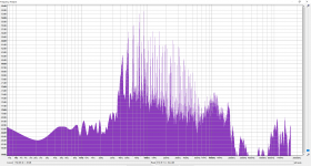
A pulse every 100ms is.. 10Hz
Practically that isn't something he would hear, right?
Maybe the issue is something else
Practically that isn't something he would hear, right?
Maybe the issue is something else
Mephisto was kind enough to post an MP4 -- and rendered in Adobe Audition, you can clearly see and hear the 100ms pulses
Hello, I hope everyone is doing well. I'm trying to figure out what I'm gonna do for the power umbilical. So far, I plan on hard wiring at the PSU end and use a cable cinch on the chassis and Neutrik powerCON combo on the RIAA end. Would it be suitable to use some 14 awg cable that I already have braided and covered with techflex?
I chatted with Wayne Colburn at lunch during 2019 Burning Amp Festival and we talked about this. I proposed the idea that Weird Is Good -- you want a connector that is found NOWHERE ELSE on any other audio gear, so your dipshit drunken party guests cannot possibly plug the cables where they don't belong. Wayne mostly agreed, and suggested these unusual connectors from Japan Aviation Electronics: list
Thanks all for the inputs and helping me.
Grounding was done as shown in the sketch, same way as you discribed itsikhefez.
Only difference would be the baseplates I used.
Maybe I should make an additional connection from the baseplate to the anodized psu case.
When I'm home at the end of the month I will check all cables again.
This is really a pain in the butt. Everything I tried didn't made a difference. Only, touching the ground from the rca inputs.
What do you think? Would it be easier to troubleshoot with a scope?
@mephjstopheles
Instead of a scope you can use a DMM with enough resolution.
I have a Keithley 2015 DMM and a Tek 724A oscilloscope and live near Waldshut-Tiengen on the German border. I also have a lab supply to change the PSU.
If that is close to you and I can keep my soul, you are happily invited to give it a try. 😀
take care
If that is close to you and I can keep my soul, you are happily invited to give it a try. 😀
Never would I take such a kind soul!😀
Thank you very much for your offer.
First i want to try the suggested inputs.
If it still doesn't work, I'll be happy to return to your offer.
If my fluke 87v has enough resolution, what would I search for?
I tested all voltages and they seem good.
With 0,1 mV you can at least measure the amplified AC signal.
With my amp I just put the Voltmeter on the output of the amp and made changes whilst observing the voltage reading. The amp was powered from an isolation transfomer and i wore gloves.
I haven´t built my Pearl yet so have little experience on a phono stage. But I guess general noise prevention applies.
- keep the phono stage as far away from any magnetic field as possible
- measure the output with inputs shorted and lid closed
- twisting (no current loops) and shield all cables
- add additional thermistors as groundbreakers
- for testing only and on isolation transformer: lift the ground connection completely
Pearl made the MAGIC SMOKE. Magic smoke smell NO BEUNO
Had a little accident with my Pearl boards the other day.
Im using a MM cartridge that puts out a massive 6mv signal which seems to result in what i think is a lot of surface noise so I've been tinkering with the second stage gain settings and the resistors next to the first stage jets. After a few iterations of the gain being lowered i still have this quiet whoosh whoosh noise (its not in time with the revolutions of the platter) that appears between tracks which i thought could of been oscillation as i had not installed C7. After installing C7 I mistakenly wired the power up the wrong way (+ to - and vice versa) which produced no pearlescent music what so ever but rather a noise akin to a very fast rattle (brrrrrrrrrrrrrrrr)
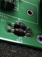
I soon noticed i had the power wired up backwards so in my idiocy i switched it off then re wired it the correct way and turned it on. The led lit up which was pleasing but then the first pair of resistors R1, R2, R30, R32 made a fizzing noise then made this huge puff of magic smoke and i quickly turned it off at the wall.
One board seems to have burnt a load more than the other and the less burnt board now plays music once i had removed the burnt resistors and bypassed the regulators and injecting power at C4 + C24 but the more burnt board just plays a loud buzz.
I switched the jets around between boards and the ones from both seem to work fine in the less burnt board which was pleasing.
My question is now which components are likely to have suffered and will need switching out ?
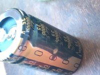
I was thinking the electrolytic caps at least and and maybe the zvp3310s, the ztx450, the wee elna .....
Had a little accident with my Pearl boards the other day.
Im using a MM cartridge that puts out a massive 6mv signal which seems to result in what i think is a lot of surface noise so I've been tinkering with the second stage gain settings and the resistors next to the first stage jets. After a few iterations of the gain being lowered i still have this quiet whoosh whoosh noise (its not in time with the revolutions of the platter) that appears between tracks which i thought could of been oscillation as i had not installed C7. After installing C7 I mistakenly wired the power up the wrong way (+ to - and vice versa) which produced no pearlescent music what so ever but rather a noise akin to a very fast rattle (brrrrrrrrrrrrrrrr)
I soon noticed i had the power wired up backwards so in my idiocy i switched it off then re wired it the correct way and turned it on. The led lit up which was pleasing but then the first pair of resistors R1, R2, R30, R32 made a fizzing noise then made this huge puff of magic smoke and i quickly turned it off at the wall.
One board seems to have burnt a load more than the other and the less burnt board now plays music once i had removed the burnt resistors and bypassed the regulators and injecting power at C4 + C24 but the more burnt board just plays a loud buzz.
I switched the jets around between boards and the ones from both seem to work fine in the less burnt board which was pleasing.
My question is now which components are likely to have suffered and will need switching out ?
I was thinking the electrolytic caps at least and and maybe the zvp3310s, the ztx450, the wee elna .....
Attachments

Pass DIY Addict
Joined 2000
Paid Member
Oh no!! I did something similar on my first amp build - an A40 about 20 years ago. I mixed up my N and P ch output devices and let a bit of magic smoke escape..
I don't have very much experience troubleshooting boards, though I would start by replacing your regulators - they are most likely to be cooked. Sounds like you got lucky with your jFets! I would then move on to replacing all of the remaining 3-legged devices. With the transistors out of the circuit, you can verify resistor values. Aside from those in the regulator, the rest of the caps are no-polar, so they should be fine.
Go slowly and methodically. Since one board works, you can make some comparisons across the boards. You'll make it work again!
During some of my resistor experiments I somehow fried the negative regulator, so half the board seemed dead but it was actually fine.
I would initially only start by replacing the regulators and any resistors that are visibly damaged.
Then start it up and take voltage measurements, most of the circuit may be fine.
I would initially only start by replacing the regulators and any resistors that are visibly damaged.
Then start it up and take voltage measurements, most of the circuit may be fine.
- Home
- Amplifiers
- Pass Labs
- Building a Pearl 2