@marlin97
I would think that RIAA caps should be accurate and precise both.
A 2% cap that was 10% off the calculated value isn't going to work.
Are the black and grey caps both Vishay? I've only seen black Vishays in the shops I frequent. What series are the grey caps?
I would think that RIAA caps should be accurate and precise both.
A 2% cap that was 10% off the calculated value isn't going to work.
Are the black and grey caps both Vishay? I've only seen black Vishays in the shops I frequent. What series are the grey caps?
I'm looking for some advice on capacitor selection. I read in an earlier post that to help stabilize the output to place a 220uF electrolytic capacitor between R14 and ground. My question is... is the value critical? I have the following in my box of parts and was wondering if any of these would suffice:
220uF 10V Nichicon Muse it's a bit bid (physically), but not sure on the voltage rating.
22uF 25V Nichicon Muse
22uF 25V Elna Silmic II
10uF 35V Elna Silmic II
I don't want to screw anything up, so if it needs to be 220uF then it'll be off to Mouser once more. I just hate having to pay the postage for a few capacitors, so I'd end up buying lots of other stuff just to justify the postage, and that would be yet another project piling up in the corner.
Many thanks,
Gary
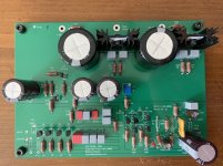
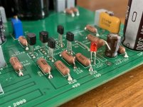
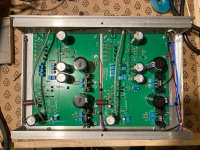
Boards all built up with just one resistor R19 (in the mail somewhere) to fit and left a gap for the capacitor between R14 and ground. Photos were taken before washing all the flux residue off.
Attachments
I'm looking for some advice on capacitor selection. I read in an earlier post that to help stabilize the output to place a 220uF electrolytic capacitor between R14 and ground. My question is... is the value critical? I have the following in my box of parts and was wondering if any of these would suffice:
220uF 10V Nichicon Muse it's a bit bid (physically), but not sure on the voltage rating.
22uF 25V Nichicon Muse
22uF 25V Elna Silmic II
10uF 35V Elna Silmic II
I don't want to screw anything up, so if it needs to be 220uF then it'll be off to Mouser once more. I just hate having to pay the postage for a few capacitors, so I'd end up buying lots of other stuff just to justify the postage, and that would be yet another project piling up in the corner.
Many thanks,
Gary
There is a post somewhere here by Wayne. Copying from my notes, he wrote:
Use a nice (Silmic) electrolytic 47uF - 470uF works fine, 25v or more and use a film bypass if you want.
I used a 100uF 35V Elna Silmic II that I had in my stash
@itsikhefez
Thanks for the pointer. I somehow missed that note from Wayne. Looks like it's off to Mouser again.
I have some 220pF and 1uF Wima PP film capacitors lying around. Would either of those be suitable as a bypass?
Thanks for the pointer. I somehow missed that note from Wayne. Looks like it's off to Mouser again.
I have some 220pF and 1uF Wima PP film capacitors lying around. Would either of those be suitable as a bypass?
I'm not sure.. I didn't bypass.. Pearl still sounds really good 🙂
I think there is some rule of thumb to bypass at 1/100? In that case 1uF may be suitable for a 100uF cap.
I think there is some rule of thumb to bypass at 1/100? In that case 1uF may be suitable for a 100uF cap.
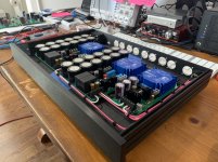
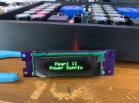
Ok, before anyone else says it.... yes, it probably is way too much just to power the Pearl II. I admit I may have gotten a little carried away and gone over the top with this. But, hey it was fun. And after all that’s what it’s all about.
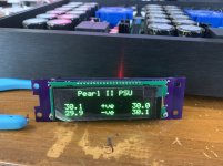
So, that said, here’s my almost complete power supply for my Pearl II. I still need to install the earth wiring from the input power connector, replace the temporary front and rear panels (hope to have the new ones in a couple of weeks or so) and install the OLED display in the front panel. But for the most part it’s done and working. I just need to get on with the Pearl II now.
So, that said, here’s my almost complete power supply for my Pearl II. I still need to install the earth wiring from the input power connector, replace the temporary front and rear panels (hope to have the new ones in a couple of weeks or so) and install the OLED display in the front panel. But for the most part it’s done and working. I just need to get on with the Pearl II now.
Attachments
Last edited:
Ummm... major overkill but I love it. Beautiful job.
How did you get the wiring so perfect? Is that solid or stranded core?
How did you get the wiring so perfect? Is that solid or stranded core?
It's 14 AWG stranded wire. I just got bored one day and straightened it as much as I could. It turned out better than the wiring I did in my BA2018 pre-amp, so I'm pleased. I guess the more you practice the better you get.
Yes, they’re my own. Way overkill I admit and until I finish my Pearl II I won’t know how well they work/sound. I used the same basic design (but less capacitance) on my BA2018 pre-amp and it sounds great, so I’m hopeful.
@stablgr
Please seriously consider posting a video detailing your wiring techniques for us mere mortals
Please seriously consider posting a video detailing your wiring techniques for us mere mortals

Well, possibly. But I would be interested, if no one else would. I understand if you don't want to make it though.
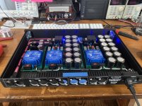
I finally finished my second build, I regretted selling my first Pearl 2 almost immediately...
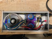
The PSU uses a small PCB that holds the rectifiers, CRC snubbers, bleeder resistors and LED's. It all fits in a Hammond 1455 case neatly for a compact PSU.
The Pearl boards are in a Par-metal 12x8x2 case, nothing fancy in terms of parts.
I want to point out some small circuit tweaks. I am using 2SK170-BL JFET's with around 8mA Idss and the voltages I observed differ from Wayne's quite a bit. There are scattered posts about this in this and the other Pearl thread.
Jack posted a few pages back simulations with the lower Idss ("A") JFET's and the "B" grade. The "B" grade result match my voltages exactly, while the "A" grade Wayne's.
I am fairly certain anyone acquiring "B" grade JFET's from the DIY audio store, or from Pass labs, will likely benefit from these minor changes.
Objective was to satisfy the following conditions:
1) JFET draw around 5mA-5.5mA
2) Q3 Vc > Vb > Ve
3) Q3 Vce > 1.1 V
4) JFET Vd > 6.5V
(these condition based on the various sources of information scattered in the thread).
My original measurements were
1) 6.2mA
2) Q3 --
Vc = 7.74V
Vb = 8.37
Ve = 7.67
3) Q3 Vce = 0.1V << 1.1V
After a bit of experimenting with R5, R10, R8, R21-R24, the following changes worked the best:
1) Increase R21-R24 to 20R. This reduces JFET's to draw 5.2mA
2) Reduce R5 from 1.5K to 1K, increasing Q3 Vc.
End result:
1) 5.2mA
2) Q3 --
Vc = 10.4V
Vb = 9.9V
Ve = 9.2V
Conditions 3 & 4 met as well.
It is also possible to reduce R10 instead of reducing R5. Depending on the value there, JFET Vd may be below 6.5V, thats why I opted with changing R5.
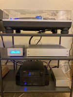
P.S -- in my rack, the PSU is on the lower shelf next to the AHB2 amp
P.S.2 -- I have extra PSU boards ... if you're interested check out the Swap Meet section
The PSU uses a small PCB that holds the rectifiers, CRC snubbers, bleeder resistors and LED's. It all fits in a Hammond 1455 case neatly for a compact PSU.
The Pearl boards are in a Par-metal 12x8x2 case, nothing fancy in terms of parts.
I want to point out some small circuit tweaks. I am using 2SK170-BL JFET's with around 8mA Idss and the voltages I observed differ from Wayne's quite a bit. There are scattered posts about this in this and the other Pearl thread.
Jack posted a few pages back simulations with the lower Idss ("A") JFET's and the "B" grade. The "B" grade result match my voltages exactly, while the "A" grade Wayne's.
I am fairly certain anyone acquiring "B" grade JFET's from the DIY audio store, or from Pass labs, will likely benefit from these minor changes.
Objective was to satisfy the following conditions:
1) JFET draw around 5mA-5.5mA
2) Q3 Vc > Vb > Ve
3) Q3 Vce > 1.1 V
4) JFET Vd > 6.5V
(these condition based on the various sources of information scattered in the thread).
My original measurements were
1) 6.2mA
2) Q3 --
Vc = 7.74V
Vb = 8.37
Ve = 7.67
3) Q3 Vce = 0.1V << 1.1V
After a bit of experimenting with R5, R10, R8, R21-R24, the following changes worked the best:
1) Increase R21-R24 to 20R. This reduces JFET's to draw 5.2mA
2) Reduce R5 from 1.5K to 1K, increasing Q3 Vc.
End result:
1) 5.2mA
2) Q3 --
Vc = 10.4V
Vb = 9.9V
Ve = 9.2V
Conditions 3 & 4 met as well.
It is also possible to reduce R10 instead of reducing R5. Depending on the value there, JFET Vd may be below 6.5V, thats why I opted with changing R5.
P.S -- in my rack, the PSU is on the lower shelf next to the AHB2 amp
P.S.2 -- I have extra PSU boards ... if you're interested check out the Swap Meet section
Attachments
I am still reading through this thread in full but wanted to ask this question before I get too far...
I intend to build a Pearl II and use a MM cart now but may be moving to a MC later on.
Can the Pearl II accommodate the usual 5mV MM carts?
I see some lower R16 to 50K and up R21-24 to 20R. Is this the best approach, what is the gain? I need about 35dB of gain from my phono stage for my set up.
I intend to build a Pearl II and use a MM cart now but may be moving to a MC later on.
Can the Pearl II accommodate the usual 5mV MM carts?
I see some lower R16 to 50K and up R21-24 to 20R. Is this the best approach, what is the gain? I need about 35dB of gain from my phono stage for my set up.
So the power line filter made no difference. Atleast the power from the house is good.
What I found out is, if I'm touching the ground from the rca input motorboating and a little bit of noise goes away.
Also if ground cable from turntable is connected I get 50hz hum.
Checking every solder joint again today and maybe replace red ground cable in riaa section. The cable is not my friend.
This has been vexxing me for days
Just a couple questions
1) what rectifier diodes are you using?
2) is the transformer an EI, or torroid?
J
- Home
- Amplifiers
- Pass Labs
- Building a Pearl 2