Pass DIY Addict
Joined 2000
Paid Member
I would only add to this: Don't rely on "visual damage" as a determinant of good vs bad resistors. The ones in the regulator obviously handle the greatest current load, so they cooked. Measure the rest of your resistors as well, just to be sure. Mostly likely, many have survived.
Last edited:
I am still reading through this thread in full but wanted to ask this question before I get too far...
I intend to build a Pearl II and use a MM cart now but may be moving to a MC later on.
Can the Pearl II accommodate the usual 5mV MM carts?
I see some lower R16 to 50K and up R21-24 to 20R. Is this the best approach, what is the gain? I need about 35dB of gain from my phono stage for my set up.
I ran my 2M Bue with no issues and it sounded great.
I also am about to set my Pearl 2 up for a MM cartridge from being set up for MC following the build guide.
The cart I’ll be using is a 2M black.
I saw someone mention increasing R14 to 1.6k ohms. Is this the only swap I should make or should I considering swapping some other resistors.
The cart I’ll be using is a 2M black.
I saw someone mention increasing R14 to 1.6k ohms. Is this the only swap I should make or should I considering swapping some other resistors.
Pass DIY Addict
Joined 2000
Paid Member
I am using a 5mV MM cartridge and I found it useful to add a 100k resistor in parallel with R16 (stuck it in the Cx location) to reduce the gain by ~10dB. Some of the albums I have seem to be recorded at a higher level than others, so this wasn't a problem with all of my albums, just a few.
Pass DIY Addict
Joined 2000
Paid Member
I'm not seeing anything in my notes about changing R14, so I assume it is just the stock value of 1k
I also am about to set my Pearl 2 up for a MM cartridge from being set up for MC following the build guide.
The cart I’ll be using is a 2M black.
I saw someone mention increasing R14 to 1.6k ohms. Is this the only swap I should make or should I considering swapping some other resistors.
Ahhhhh, a Black! I have a Bronze now but have not been able to spin it yet.
Mine handles a 10mV output Shure M44-7 without a problem.
Prodigious output, @5cm/sec.!
Ok I've read through this entire thread now, what a great resource. I do have a few outstanding questions before I get to ordering parts.
1. is there any advantage/disadvantage of using a CL-60 vs the bridge rectifier for the audio ground?
2. Does anyone know the Quasimodo snubber values for the Antek AS-0522 - 50VA 22V transformer?
3. Anyone have part numbers for mica insulator pads and washers for TO-220 devices?
4. If the binding post is not insulated then I assume I would not take a wire back to the chassis?
5. On the note of grounding I thought I read that the chassis standoff points are connected to ground and as such a insolated standoff should be used. Is that true? Seems weird if so...
6. If doing the R14 cap mod to stablilize DC offset would you bother buying the C13 and C8 output caps (expensive!)?
7. What does everyone like in terms of a PSU PCB? I want something small so I can build the PSU in a small chassis. Was originally going to use the stores UPS PCB but it is on the larger side.
1. Wayne designed it with the bridge, as it’s quieter.
2. Check the Quasimodo results thread.
3. Not needed. But check Amazon, they have kits that have both together in reasonable quantities.
4. ?
5. The PCB mounting holes are not connected to PCB ground.
6. Expensive capacitors mostly just make your wallet lighter.
7. You don’t actually need a PCB. Just a bridge and a couple of caps. Yes, the universal is enormous for this job.
@6L6
Actually I took Q-6 to be more about the need for an output cap (the best cap is... ) than a matter of money (~$0.50 + $0.84 is hardly expensive) and it's something I wondered too.
Can the added cap at R14 reduce the need/value of the output, perhaps so that a small film cap would do?
Actually I took Q-6 to be more about the need for an output cap (the best cap is... ) than a matter of money (~$0.50 + $0.84 is hardly expensive) and it's something I wondered too.
Can the added cap at R14 reduce the need/value of the output, perhaps so that a small film cap would do?
Last edited:
1. Wayne designed it with the bridge, as it’s quieter.
2. Check the Quasimodo results thread.
3. Not needed. But check Amazon, they have kits that have both together in reasonable quantities.
4. ?
5. The PCB mounting holes are not connected to PCB ground.
6. Expensive capacitors mostly just make your wallet lighter.
7. You don’t actually need a PCB. Just a bridge and a couple of caps. Yes, the universal is enormous for this job.
Thanks 6L6!
In regards to question #4 I was asking that in reference to your grounding scheme drawing. Your drawing shows the PCB grounds going to the binding post then a wire runs from there to the chassis ground. I assume the wire going from the binding post to the chassis ground is not needed if the binding post is not insulated (ie it is a chassis ground point).
Hi,
for R14=1k if R16=50k, gain will be 45dB instead of 55dB.
for R16=100k if R14=330R, gain will be 65dB.
Can I decrease R16 to 25k and let R14=1k to have 35dB gain ?
Can I increase R16 to 200k and let R14=1k to have 65dB gain ?
Can I increase R16 to 200k and decrease R14 to 330R to have 75dB gain ?
Thanks
Damien
Mine handles a 10mV output Shure M44-7 without a problem.
Well, maybe.
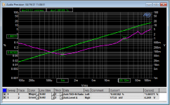
Output @5mV/sec is 9.5mV @1kHz. At 4kHz the output is supposed to be 6.6dB higher, attenuated by the passive RIAA network. As Shure demonstrated, output at 4kHz can be 10 - 14 times higher!
In any event, here's a chart of THD% (left vertical axis) vs input level (horizontal axis) and output level (right vertical axis) at 4kHz
Attachments
Pass DIY Addict
Joined 2000
Paid Member
6. If doing the R14 cap mod to stablilize DC offset would you bother buying the C13 and C8 output caps (expensive!)?
In my original build, I put the recommend cap in the C13 position and left C8 open. After I added the cap to ground after R14, I installed a jumper across C8 pads, effectively removing C13 from the circuit. No problems at all in the years since doing this. Though, you do want to power up the Pearl 2 FIRST and any other preamp/amps SECOND as it can send a DC pulse while it powers up.
Ok, thanks for the info!In my original build, I put the recommend cap in the C13 position and left C8 open. After I added the cap to ground after R14, I installed a jumper across C8 pads, effectively removing C13 from the circuit. No problems at all in the years since doing this. Though, you do want to power up the Pearl 2 FIRST and any other preamp/amps SECOND as it can send a DC pulse while it powers up.
The Pearl 2 would be feeding a 12B4 tube linestage preamp. The 12B4 preamp is muted for the first 30 seconds while the heaters warm up. Not sure the implications of some DC on the tube's grids...
A question:
Is it worth adding a RC filter to the external PSU? I know the existing PSU as a whole is a CRC but would it be worth it to add a RC in the external PSU enclosure, effectively creating a toal CRCRC?
Pass DIY Addict
Joined 2000
Paid Member
It certainly can't hurt, but I'm not sure how much it helps as this stage comes before the on-board voltage regulators. I currently have CRCRC in my external power supply, then it goes thru an umbilical into the Pearl 2 chassis. Then, I have one of Salas' shunt regulators feeding the boards, so things are pretty quiet...
The point of the chart I posted -- the THD% at 4kHz starts to get nasty ~25mV input -- this is the fundamental for cymbals, certain drums (snare) and violins -- maybe clarinets. That's why I would tame the 2nd stage of the Pearl for high output carts.
Of course, electronic music is in another realm entirely, but not usually on vinyl!
Of course, electronic music is in another realm entirely, but not usually on vinyl!
- Home
- Amplifiers
- Pass Labs
- Building a Pearl 2