tayj10 you could also use capacitor clamps (the ones that look like hose clamps) and bolt them to the bottom of the chassis.
--severely rolled-off highs.
This may have been asked before....but are you sure you have the caps in the RIAA section in their correct positions?
This may have been asked before....but are you sure you have the caps in the RIAA section in their correct positions?
Yes, I'm pretty certain that everything is in the right place. I posted pictures previously.
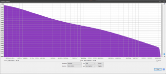
I played some white noise through my Pearl 2, and the resulting spectrum analysis from Audacity illustrates that the Pearl 2 seems to be working properly. I don't have a reverse RIAA, but at a quick glance it seems to fit the RIAA curve pretty accurately from 20-20kHz.
So, this seems like it would point to a capacitance/resistance loading issue with my cart.
My cart should need 150-300 pF capacitance and 47k resistance loading according to Ortofon.
I've tried 0-300 pF loading in C22, but nothing helps.
I've confirmed that my Pearl 2 reads 47k on the inputs with my DMM.
If the problem were that the tables and cables had too much capacitance in the wiring, I would think I would have the same issue with an NAD pre-amp that has 47k/100pF, but it works just fine. It also works fine on my Onkyo surround receiver.
My cartridge just doesn't work with two different Pearl 2s on two separate turn tables.
I'm nearly to the point of just getting a different cartridge, and even if that is the solution, I'd still like to know why this is happening.
Attachments
Those are off my invoice, but I check all the part numbers on the bags when the order came in, and the values printed on the sides match up.
My experience is kw and kx nichicon have very dark rolled off high.. Try using normal caps like nichicon pw
I played some white noise through my Pearl 2, and the resulting spectrum analysis from Audacity illustrates that the Pearl 2 seems to be working properly. I don't have a reverse RIAA, but at a quick glance it seems to fit the RIAA curve pretty accurately from 20-20kHz.
So, this seems like it would point to a capacitance/resistance loading issue with my cart.
My cart should need 150-300 pF capacitance and 47k resistance loading according to Ortofon.
I've tried 0-300 pF loading in C22, but nothing helps.
I've confirmed that my Pearl 2 reads 47k on the inputs with my DMM.
If the problem were that the tables and cables had too much capacitance in the wiring, I would think I would have the same issue with an NAD pre-amp that has 47k/100pF, but it works just fine. It also works fine on my Onkyo surround receiver.
My cartridge just doesn't work with two different Pearl 2s on two separate turn tables.
I'm nearly to the point of just getting a different cartridge, and even if that is the solution, I'd still like to know why this is happening.
Loading a MM cartridge at 100 ohms will have a huge impact on the sound. The capacitance/resistance changes you're talking about will have a tiny impact, so I'd look elsewhere. It could be that you're hearing accurate sound and it is not what you're used to. It's happened to me.
Loading a MM cartridge at 100 ohms will have a huge impact on the sound. The capacitance/resistance changes you're talking about will have a tiny impact, so I'd look elsewhere.
I'm not sure what you mean. Do you mean omitting C22 will have a huge impact vs. 100 pF in place, but changing C22 from 100-300pF will have little effect? I've never changed the loading resistor--it's always had 47 kOhms in R19 with R20 omitted.
Yeah, I think they're still available on Peter Daniel's website.
Thanks! I'd definitely feel more comfortable knowing there's no way the caps/board could get knocked loose and cause a short.
Yes they are,
just bought a pair.
So...
It turns out that my cartridge was defective. I purchased an Ortofon Red, mounted it on my table and I didn't hear the problem. I swapped to my blue stylus and it sounds great!
I still don't understand why the problem only manifested on the Pearl 2, but at this point I don't really care. It works now and I'm beyond happy! Now I can do the final wire clean up inside the enclosure.
Thanks to everyone who took the time to help me figure out what the problem was, especially 6L6!
Wow...that is crazy. So the body/engine was actually defective. I'm glad
you found the problem, and also that you can still use the Blue's stylus.
Enjoy your Pearl 2.
you found the problem, and also that you can still use the Blue's stylus.
Enjoy your Pearl 2.
Strange voltage at P1 test point
Hello there,
Thank you in advance for your expertise.
I have been studying this Pearl 2 phono stage project for quite a while, looked at almost all of you guys’ discussions, detailed instructions, and beautiful pictures. Finally, I plunged myself into this diy project and encountered very strange (probably serious?) problem. I followed Jim’s advice and got Antec AS0522 transformer. Then, through 2 full wave bridge rectifiers, two banks of 2 x 10,000 uF caps (total of 40,000uF), 2 bleeder 22kOhms resisters, and two 0.47 ohm PI resistors, I got + 28.8 V and + 29.3 V unregulated and about the same voltages for regulated.
Then, when I checked the P1 test point (the pad that has “set P1 for 0 volts DC), I got negative (-) 23.4 volts (yes, volts and NOT mV). Turning the P1 trimmer dial did not change the above voltage at the P1 test point.
The same high voltage reading at P1 test point was also noted at the other PCB as well. Adjusting P1 trimmer on the second board didn’t not change the voltage at all. As far as the resistors and capacitors, I did check there values carefully prior to stuffing the boards. I didn’t check the transistors prior to assembly however.
My questions to you:
1. Did I install the P1 trimmer wrong? I did order a “similar Value” 5K Bourn trimmer with 3 pins in a straight line (instead of the one with the center pin offset a little bit). Both Mouser and Digi-Key didn’t have the trimmer with central offset pin at that time. Moreover, I thought these trimmers were interchangeable, just bend the center pin over a little bit to fit. Maybe I am wrong.
2. What else should I check to troubleshoot this problem?
3. Did I damage other components (i.e. the chip set) by having such high negative voltage at this point?
4. Were the regulated and unregulated DC voltages too low for the transistors to function properly? How can I increase these voltages?
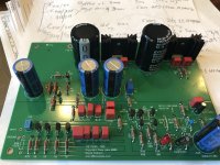
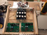
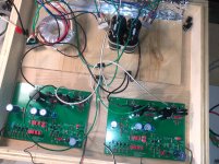
I will post some pictures of my boards and PSU on the next post.
Thanks a million,
Quan
Hello there,
Thank you in advance for your expertise.
I have been studying this Pearl 2 phono stage project for quite a while, looked at almost all of you guys’ discussions, detailed instructions, and beautiful pictures. Finally, I plunged myself into this diy project and encountered very strange (probably serious?) problem. I followed Jim’s advice and got Antec AS0522 transformer. Then, through 2 full wave bridge rectifiers, two banks of 2 x 10,000 uF caps (total of 40,000uF), 2 bleeder 22kOhms resisters, and two 0.47 ohm PI resistors, I got + 28.8 V and + 29.3 V unregulated and about the same voltages for regulated.
Then, when I checked the P1 test point (the pad that has “set P1 for 0 volts DC), I got negative (-) 23.4 volts (yes, volts and NOT mV). Turning the P1 trimmer dial did not change the above voltage at the P1 test point.
The same high voltage reading at P1 test point was also noted at the other PCB as well. Adjusting P1 trimmer on the second board didn’t not change the voltage at all. As far as the resistors and capacitors, I did check there values carefully prior to stuffing the boards. I didn’t check the transistors prior to assembly however.
My questions to you:
1. Did I install the P1 trimmer wrong? I did order a “similar Value” 5K Bourn trimmer with 3 pins in a straight line (instead of the one with the center pin offset a little bit). Both Mouser and Digi-Key didn’t have the trimmer with central offset pin at that time. Moreover, I thought these trimmers were interchangeable, just bend the center pin over a little bit to fit. Maybe I am wrong.
2. What else should I check to troubleshoot this problem?
3. Did I damage other components (i.e. the chip set) by having such high negative voltage at this point?
4. Were the regulated and unregulated DC voltages too low for the transistors to function properly? How can I increase these voltages?
I will post some pictures of my boards and PSU on the next post.
Thanks a million,
Quan
About the 5k not, I've done something similar before. Unless the pot was damaged while bending the middle leg, I don't see a problem.
~+/-29V should be adequate for the voltage regulators so your quoted regulated
values look funny. Where are you measuring the regulated voltages?
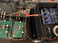
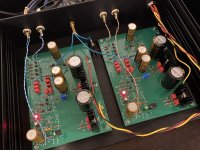
Can you post well-lit large photos of the boards and PS? Perhaps someone can
spot something.
~+/-29V should be adequate for the voltage regulators so your quoted regulated
values look funny. Where are you measuring the regulated voltages?
Can you post well-lit large photos of the boards and PS? Perhaps someone can
spot something.
I got + 28.8 V and + 29.3 V unregulated and about the same voltages for regulated.
Your unregulated voltage seems OK (I used the same transformer in my recent build)
Your regulated voltage should be around +24v and -24v within a volt or so. Measure this from R3/R4 (positive) and R31/R33 (negative) to ground on each board.
I would recommend removing those 4x 10R resistors and making sure your regulator section is working OK before you energize the rest of the circuit.
You will not believe this. Wild voltages at P1 test pads (cont.)
Dennis, myMindinside and 6L6,
Thank you for your quick responses. You are correct! The 5k trimmer pots should be fine. My unregulated voltages were not equal but close (+28.8 V and - 29.3 V). My regulated voltages, as far as I remember, were roughly +/- 24 V at R3/4 and R31/33, respectively.
6L6, I followed your instructions to a tee; therefore, am quite confident that the boards stuffed well and connections are correct. Super careful with the static sensitive ZVP3310 during installation. Also, bought a few extra for a safety net.
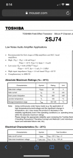
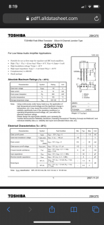
Gents, you will not believe this. I researched the entire web to see who else had my same problem, wild high voltages at P1 test pad -23.5 Volts (which should theoretically be close to 0 volt). Guess what, a few years back, there was a post on this very forum, stating a very similar symptom of wild voltages at various test points which made no sense whatsoever. The original poster got a tip from some diyAudio guru (maybe one of you guys ), pointing out that the transistors could be the culprit. He looked at his matched JFETs which he got from PassDIY. His JFETs were J74 bl9c, which I also received and installed. These JFETs were not comparable to or interchangeable with 2SK370. I don't think they are even close.
No wonder why my voltages are all out of quack. This is a clear case of rookie mistake. Never trust the senders (whether PassDIY, Mouser, or DigiKey). Always always check the components yourself, in terms of their types, values, strength, wattage, voltage, ESR, temperature etc.... I checked every component before stuffing, except these transistors, and I suffered some setbacks, hopefully reversible. Time will tell.
I emailed Anastasia from PassDIY who graciously acknowledged the possible mixup and promised to send me a new matched set of JFETs. I will update you guys with some good news after the chip exchange. I really hope I didn't fry any other components by the large swing in voltages, caused by the mixup. Please wish me luck.
Thank you again,
Quan
Dennis, myMindinside and 6L6,
Thank you for your quick responses. You are correct! The 5k trimmer pots should be fine. My unregulated voltages were not equal but close (+28.8 V and - 29.3 V). My regulated voltages, as far as I remember, were roughly +/- 24 V at R3/4 and R31/33, respectively.
6L6, I followed your instructions to a tee; therefore, am quite confident that the boards stuffed well and connections are correct. Super careful with the static sensitive ZVP3310 during installation. Also, bought a few extra for a safety net.
Gents, you will not believe this. I researched the entire web to see who else had my same problem, wild high voltages at P1 test pad -23.5 Volts (which should theoretically be close to 0 volt). Guess what, a few years back, there was a post on this very forum, stating a very similar symptom of wild voltages at various test points which made no sense whatsoever. The original poster got a tip from some diyAudio guru (maybe one of you guys
), pointing out that the transistors could be the culprit. He looked at his matched JFETs which he got from PassDIY. His JFETs were J74 bl9c, which I also received and installed. These JFETs were not comparable to or interchangeable with 2SK370. I don't think they are even close.No wonder why my voltages are all out of quack. This is a clear case of rookie mistake. Never trust the senders (whether PassDIY, Mouser, or DigiKey). Always always check the components yourself, in terms of their types, values, strength, wattage, voltage, ESR, temperature etc.... I checked every component before stuffing, except these transistors, and I suffered some setbacks, hopefully reversible. Time will tell.
I emailed Anastasia from PassDIY who graciously acknowledged the possible mixup and promised to send me a new matched set of JFETs. I will update you guys with some good news after the chip exchange. I really hope I didn't fry any other components by the large swing in voltages, caused by the mixup. Please wish me luck.
Thank you again,
Quan
Attachments

I think you'll be fine. In any case, all the other active components are cheap
and readily available.
While you wait for the new jfets (probably 2sk170 or 2sk370) to arrive, I suggest
you carefully desolder the existing 2sj74 parts and test them to see if they're
still good. These jfets are rare and I hope they can be reused in other projects.
and readily available.
While you wait for the new jfets (probably 2sk170 or 2sk370) to arrive, I suggest
you carefully desolder the existing 2sj74 parts and test them to see if they're
still good. These jfets are rare and I hope they can be reused in other projects.
Just finished soldering, testing, and hooking the Pearl 2 into my system. So far I’m really liking the sound. Not sure about him or noise since the kids jump house was on and drowned out some of the sound. I’ll report back on that later. Right now it feels good to have this build in the books. Thanks to everyone and to itsikhefez for the great layout inspiration on the back panel.
Attachments
Update on hum and noise. No hum at all, even with the super short umbilical I have on there right now. I do hear some hiss at full volume but barely audible at normal listening volume.
- Home
- Amplifiers
- Pass Labs
- Building a Pearl 2